BB
BB
M
ASSEMBLY INSTRUCTIONS
Hardware Used
x 2
5/32-32 x 3/8 in.
Screw
Hardware Used
x 4
5/32-32 x 3/8 in.
Screw
5
BB
Hardware Used
1/4-20 x 3/8 in.
Screw
x 4
AA
AA
W
O
CC
X
B1
P
CC
AA
U
AA
P
B1
X
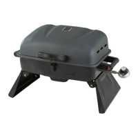
6. Install LP tank barrier bar
Attach the LP tank barrier bar (O) as the arrows indicate
to the cart back panel (I) and the cart base (W) using
2 5/32-32 x 3/8 in. screws (AA) as shown in Fig. 6. The right
install direction should be same as the indicate.
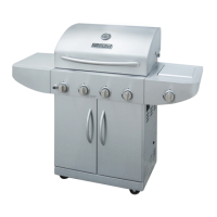
7. Install cart support beam
Attach the cart support beam (X) to the left and
right side cart panels (P and B1) using 4 1/4-20 x 3/8 in.
screws (CC) as shown in Fig. 7.
Make sure the magnets on the cart support beam (X)
face outward and the holes face downward
when assembling.
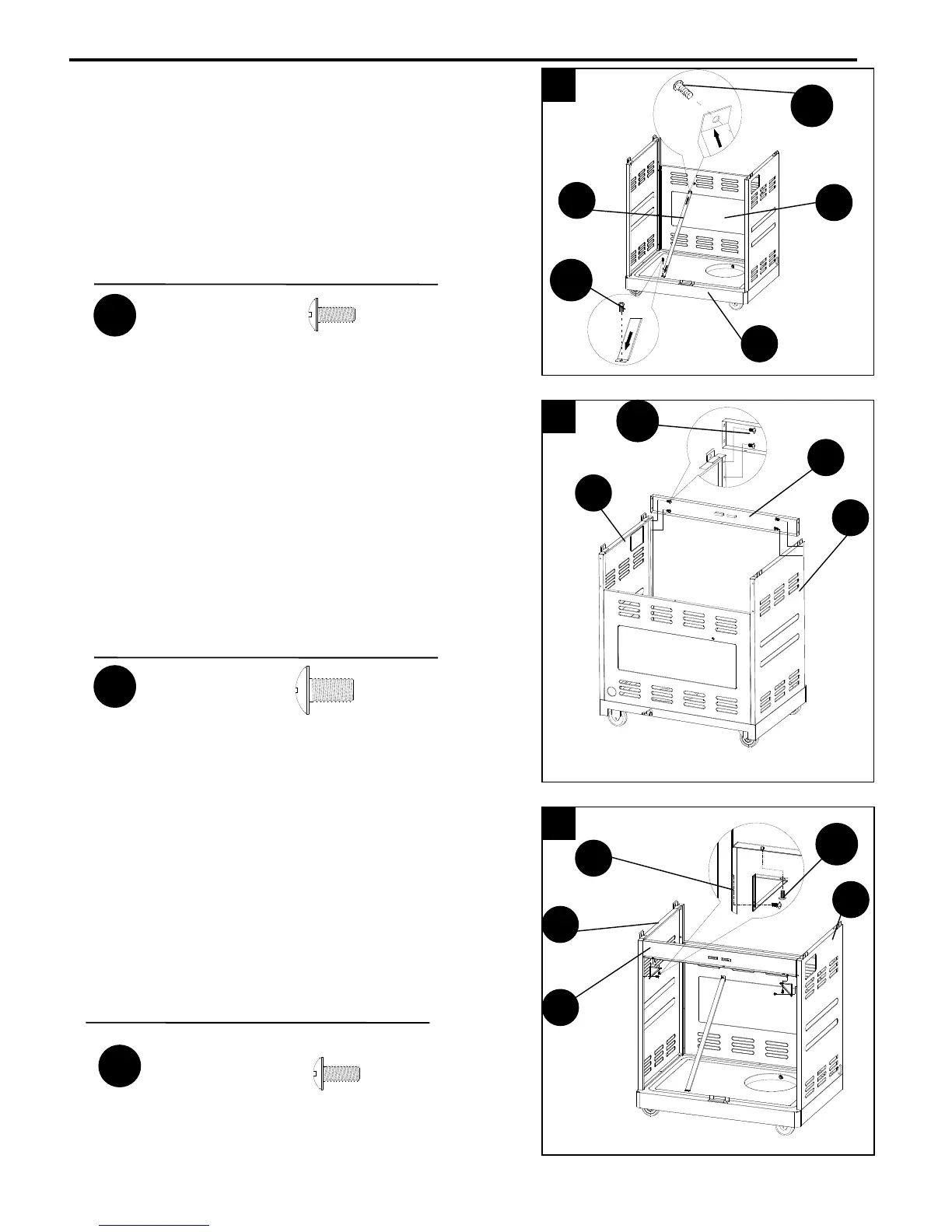
8. Install cart support brackets
Attach the cart support brackets (U) to the cart
support beam (X) and to the left and right side
cart panels (P and B1) using 4 5/32-32 x 3/8in. screws
(AA) as shown in Fig. 8.
Install all screws loosely first and then tighten.
10
7
6
8
I
AA