16
G
ASSEMBLY INSTRUCTIONS
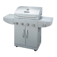
18. Install side burner valve
a) Loosen but do not remove the two pre-installed
screws from the side burner valve as shown in Fig. 18A.
b) Insert the side burner valve screws through the
keyhole slots in the front of the side burner shelf and
then slide the valve upward so the screws rest in the
small section of the keyhole slots.
c) Place the control knob bezel (G) keyhole slots over the
side burner valve screws. Let the bezel (G) slide down so
that the screws rest in the small section of the keyhole
slots and then tighten the screws. Refer to Fig. 18A.
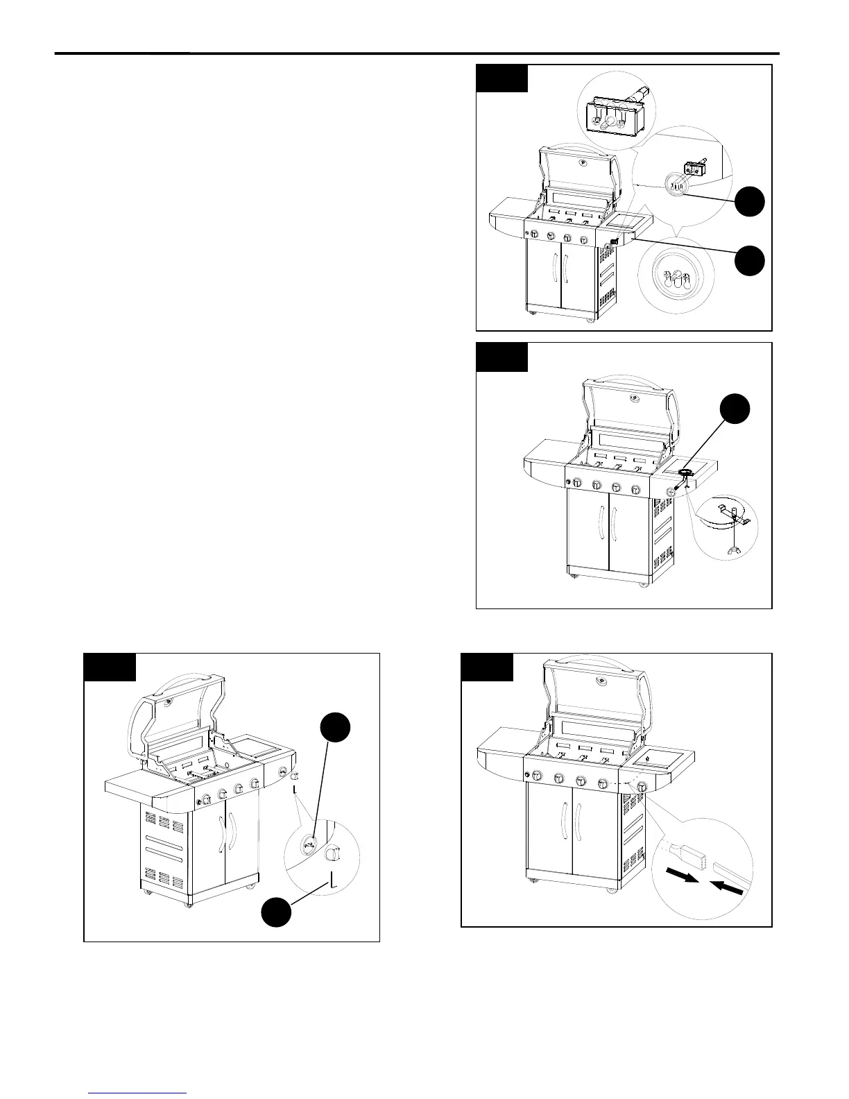
d) Remove the side burner cooking grate and then
remove the wing nut that attaches the side burner (E1).
Insert the side burner tube over the side burner valve
orifice and then reattach the side burner wing nut as
shown in Fig.18B.
e) Push the control knob (H) onto the side burner
control valve stem and then secure using the Allen wrench
(FF) as shown in Fig. 18C.
f) Reinstall side burner (E1) and side burner grate.
g) Attach electronic ignition wire to the side burner
electrode located under the side shelf as shown
in Fig. 18D.
15
18A
18B
18C
G
E
A
18D
FF
E1