CAUTION: Your product's miter cut and bevel cut angles have been preset at the factory but can and
will be misaligned by rough handling and transportation. It is essential that your new miter saw be realigned before use.
Please adhere to the following resetting instructions.
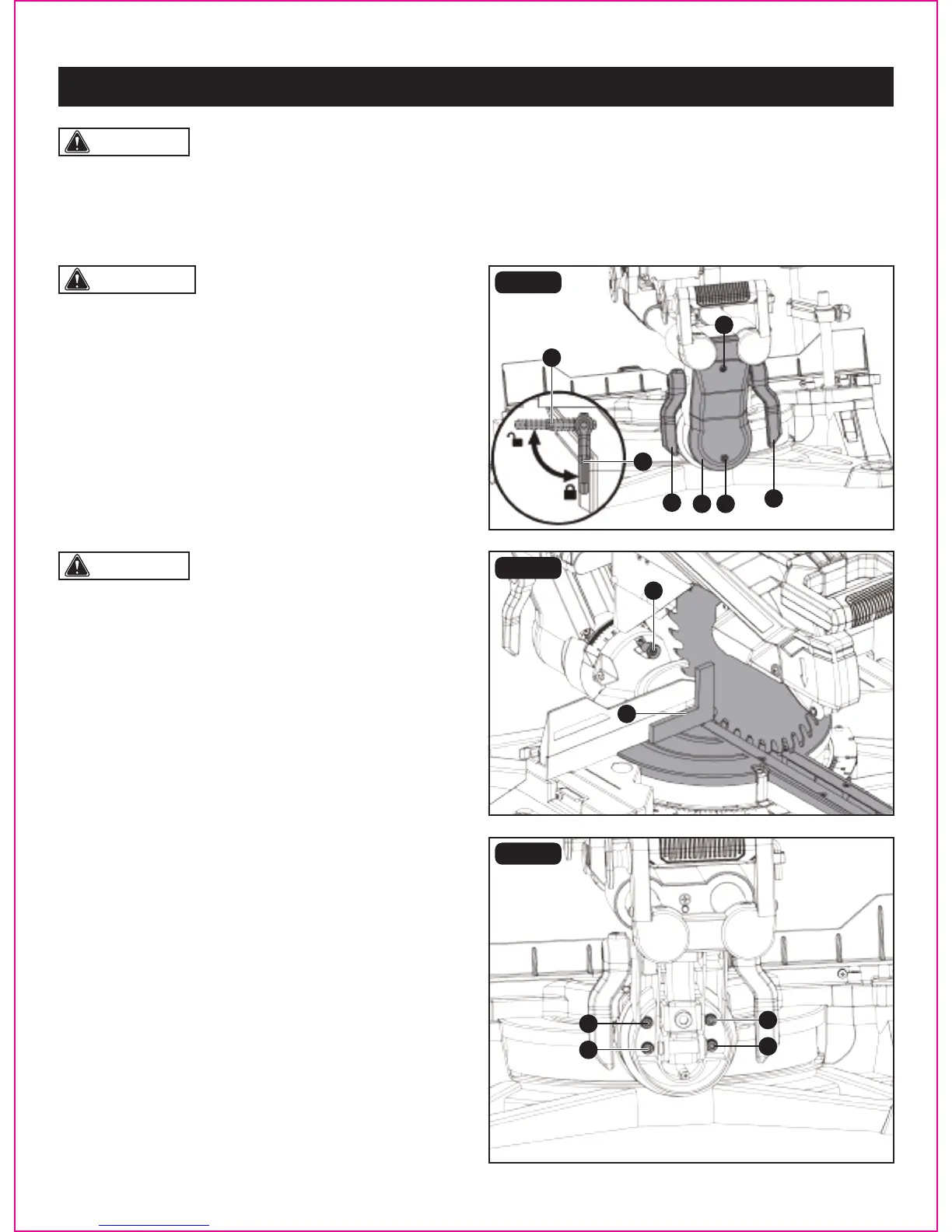
CAUTION: Make sure that the square contacts the
at part of the saw blade, not the blade teeth.
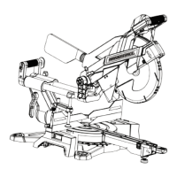
90° (0°) Bevel adjustment (Fig. 12a-12c)
• Loosen two bevel lock levers (A) by turning them to back
of the saw and tilt the cutting arm while pushing in the
bevel detent pin (B) (Fig. 12b) in against the 0° bevel stop.
Tighten the bevel lock levers by turning them to front of
the saw.
• Place a framing square (C) on the miter table with one leg
of the square against the table and slide the other leg of
the square against the at part of the saw blade.
• If the blade is not 0° to the miter table, loosen two cross
screws (D) (Fig. 12a) on the back cover (E) of the miter saw
and remove the back cover (E).
• Loosen the four adjustment bolts (F) (Fig. 12c) at the rear
of the unit with 5mm hex key (not included). Unlock two
bevel lock levers (A) and adjust the cutting arm zero degrees
to the table. After alignment is achieved, tighten the four
adjustment bolts (F) and tighten the two bevel lock levers
to secure the cutting head.
WARNING: To avoid injury from unexpected starting
or electrical shock, make sure the trigger is released and
remove the power cord from the power source.
FIG. 12a
FIG. 12b
FIG. 12c
BEVEL STOP ADJUSTMENT (FIG. 12a-12e)
Page 21
ADJUSTMENT
A
A
A
DE
D
B
C
A
F
F
F
F