8
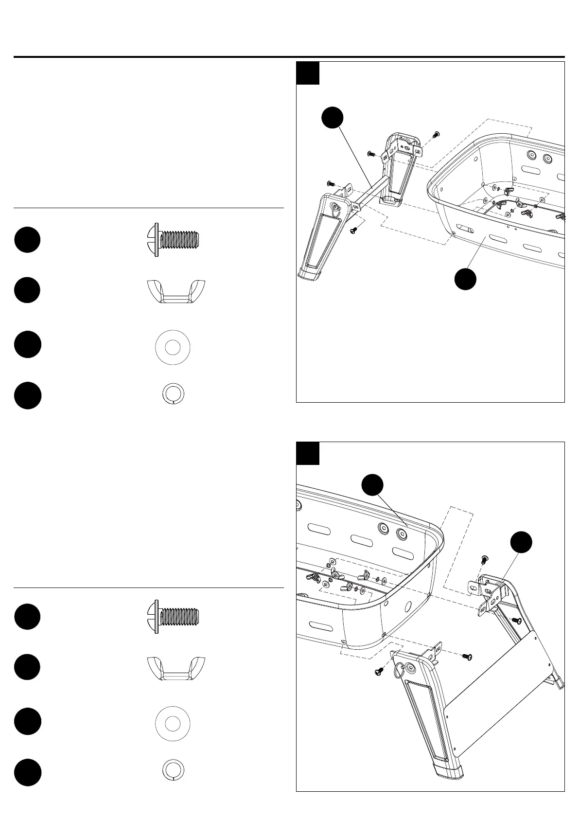
Step 3: Attach Left Leg Assembly
Align the holes in the left leg assembly (O) and
bottom bowl (K). Then attach it onto the bottom bowl
(K) with four M5x12 screws (BB), M5 wing nuts (DD),
Ø5 washers (EE) and Ø5 lock washers (GG).
Note: Just tighten all screws after installing the last
one.
Hardware Used
3
K
ASSEMBLY INSTRUCTIONS
O
Step 4: Attach Right Leg Assembly
Align the holes in the right leg assembly (P) and
bottom bowl (K). Then attach it onto the bottom bowl
(K) with four M5x12 screws (BB), M5 wing nuts (DD),
Ø5 washers (EE) and Ø5 lock washers (GG).
Note: Just tighten all screws after installing the last
one.
Hardware Used
4
K
P
M5x12
Screw
BB
x 4
M5x12
Screw
BB
x 4
Ø5
Washer
EE
x 4
Ø5
Washer
EE
x 4
Ø5
Lock Washer
GG
x 4
Ø5
Lock Washer
GG
x 4
M5
Wing Nut
DD
x 4
M5
Wing Nut
DD
x 4