NEVER LEAVE HEATER UNATTENDED WHILE BURNING OR
WHILE CONNECTED TO A POWER SOURCE
© 2014, Pinnacle Products International, Inc. Kerosene Forced Air Heater User’s Manual
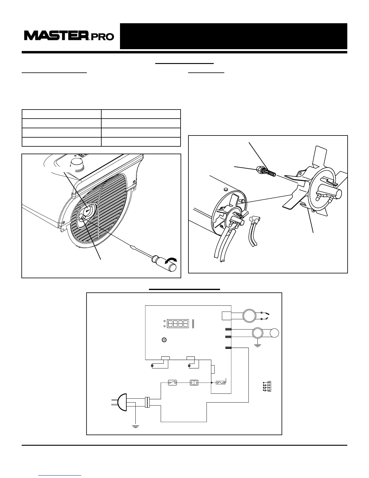
Wiring Diagram
CAPACITOR
SPARKPLUG
BLUE
EARTH
GREEN
AC 120V
60Hz
POWER
PLUG
CN2
BLUE
BLUE
WHITE
BLACK
BLACK
(TEMP.CONTROL)
THERMOSTAT
BLACK
BLACK
SWITCH
POWER
PHOTO CELL
CD5
SENSOR
ROOM
CN3
CONTROL
LIMIT
5A/250VAC
ACN1
BLACK
FUSE
R-TH
MOTOR02
ACN2
WHITE
GREEN
EARTH
CONTROL PCB
RUN
TIMER
MOTOR01
CN1
IGNITOR
BLACK
BLUE
BLUE
MOTOR
PUMP
BLUE
BLACK
RED
EMPTY
FULL
CN4
LEVEL
SWITCH
CON4
Maintenance
PUMP PRESSURE:
While heater is operating, turn adjusting screw
clockwise to increase, counter-clockwise to
decrease pressure. Correct pump pressure is as
follows:
Model Number Pump Pressure
MHP-135-KFA 5.0 PSI
MHP-190-KFA 7.5 PSI
MHP-215-KFA 9.0 PSI
Tolerance ± 10%
NOZZLES:
Nozzles should be cleaned or replaced at least
once per heating season. Contaminated fuel could
make this necessary immediately. To clean dirt
from nozzle, blow compressed air through nozzle
front. It may be necessary to soak the nozzle in
1-K kerosene to loosen any dirt particles.
Figure 13
Adjusting Screw
Pressure Valve
Figure 14
Nozzle
Nozzle Face
Burner Head
10
Figure 15: MHP-135-KFA / MHP-190-KFA / MHP-215-KFA
 Loading...