47DO NOT DIVE.
ELECTRICAL REQUIREMENTS
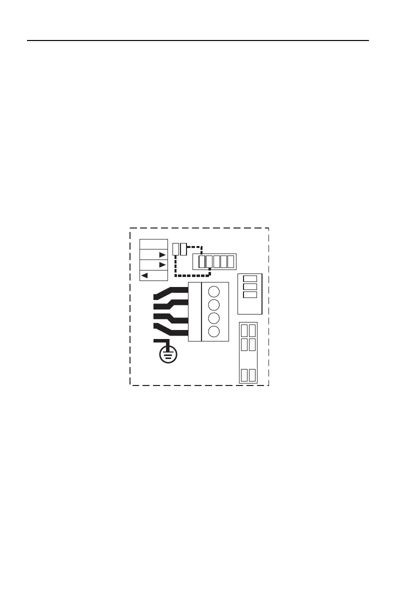
MS6013XE HOOK-UP
OPTIONAL HOOKUP – 3 SERVICE
(Figure 2)
3-Phase Service, TN and TT Electrical Systems 5 Wires (3 Lines + 1 Neutral + 1 Protective Earth)*.
Protective Earth wire (Green/Yellow) must be connected to system ground terminal as marked.
1. Remove all jumper wires as indicated by dotted lines in Figure 1 (previous page).
2. Only reinstall jumper wires as indicated by dotted lines in Figure 2.
IMPORTANT – EACH SERVICE MUST INCLUDE A NEUTRAL WIRE, WITH A LINE TO
NEUTRAL VOLTAGE OF 230VAC.
Heat Disable dip switches (Switch Bank S1, A2-A4) must be evaluated to prevent the spa maximum
ampacity from exceeding the service maximum ampacity per line (L1, L2 & L3).
TB1
4
1
2
3
1
Unfused
J41
J60
J51
J52
J198
J12
J36
J53
J58
GRN
BLU
BRN
230V
1þ
1x32A
1
Unfused
J51
J52
J198
GRN
TB1
4
1
2
3
4
J45
J54
J77
J78
J79
J41
J60
REMOVE
JUMPER WIRES
J51-J58
J52-J36
J12
J36
J53
J58
J62
J88
3
230V 3þ 3x16A
A2
A3
OFF
ON
A5
2 BRN
BLU
1 BRN
3 BRN
Figure 2
* Wiring must be sized to spa specification. Spa rated maximum ampacity cannot exceed the service
maximum ampacity. This does not represent an option to the Installer. See Model Specifications
page for electrical requirements by spa model.
CAUTION – RCD will vary by manufacturer of RCD. Improper wiring of RCD
may result in permanent damage to spa control pack. Repair/replacement of
spa system box is not covered under warranty when damage results from
improper wiring. Actual wire attachment points on the Spa Control Pack may
vary. Always refer to the wiring diagram inside the Spa Control Pack for proper
power connection.