9
GB
FUEL AND AIR LINE REPLACEMENT AND
PROPER ROUTING
1. Remove upper shell (see page 7).
2. Remove side cover screws using 5/16” nut driver.
3. Remove side cover.
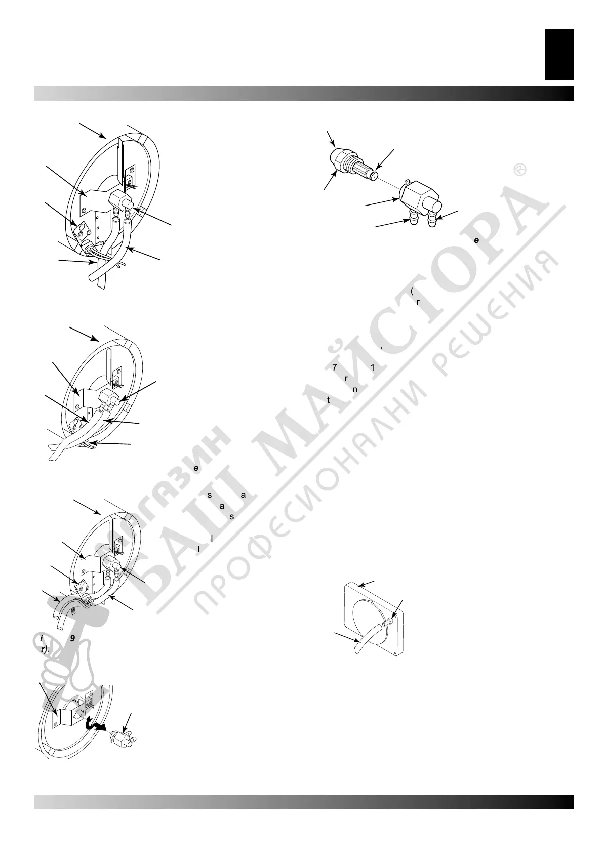
4. nspect fuel and air line hoses for cracks and/or holes. If fuel
line hose is damaged, disconnect from nozzle adapter (see
Figure 17, 18, or 19) and from fuel lter (see page 6). If air line
hose is damaged, disconnect from nozzle adapter (see Figure
17, 18, or 19) and from barb tting on pump end cover (see
Figure 22).
5.Install new air and/or fuel line. Attach one end of air line hose
to barb tting on pump end cover (see Figure 22) and the
other end to nozzle adapter (see Figure 17, 18, or 19). Attach
one end of fuel line hose to fuel lter (see page 6) and the
other end to nozzle adapter (see Figure 17, 18, or 19).
For 35.000, 64.000 and 70.000 Btu/Hr model heaters, route
air and fuel lines approximately as shown in Figure 17.
Note: Hoses are not to be touching photocell bracket.
For 100.000 Btu/Hr model heater, route air and fuel lines
approximately as shown in Figure 18.
Note: Hoses are not to be touching photocell bracket.
For 150.000 Btu/Hr model heater, route air and fuel lines
approximately as shown in Figure 19.
Note: Hoses are not to be touching photocell bracket.
6. Replace side cover.
7.Replace upper shell and fan guard (see page 7).
A.
B.
C.
D.
E.
F.
A. Combustion Cham-
ber
B. Nozzle/Adapter As-
sembly
C. Fuel Line Hose
D. Air Line Hose
E. Photocell Bracket
F. Nozzle Adapter
Bracket
Figure 17 – Removing air and fuel line hoses, 35.000,
64.000 and 70.000 Btu/Hr Models.
A.
B.
C.
D.
E.
F.
A. Combustion Chamber
B. Nozzle/Adapter As-
sembly
C. Fuel Line Hose
D. Photocell Bracket
E. Air Line Hose
F. Nozzle Adapter Bracket
Figure 18 – Removing air and fuel line hoses, (100.000
Btu/Hr).
A.
B.
C.
D.
E.
F.
A. Combustion Chamber
B. Nozzle/Adapter Assembly
C. Fuel Line Hose
D. Air Line Hose
E. Photocell Bracket
F. Nozzle Adapter Bracket
Figure 19 – Removing air and fuel line hoses (150.000 Btu/
Hr).
A.
B.
A. Combustion Chamber
B. Nozzle/Adapter Assembly
Figure 20 – Removing nozzle/adapter assembly
A.
B.
C.
D.
E.
F.
A. Nozzle face
B. Nozzle seal
C. Fuel line tting
D. Air line tting
E. Nozzle adapter
F. Nozzle
Figure 21 – Nozzle and nozzle adapter.
A.
B.
C.
A. Pump end cover
B. Barb tting
C. Air hose
Figure 22 – Air hose to barb itting
Continued
SERVICE PROCEDURES