3
GB
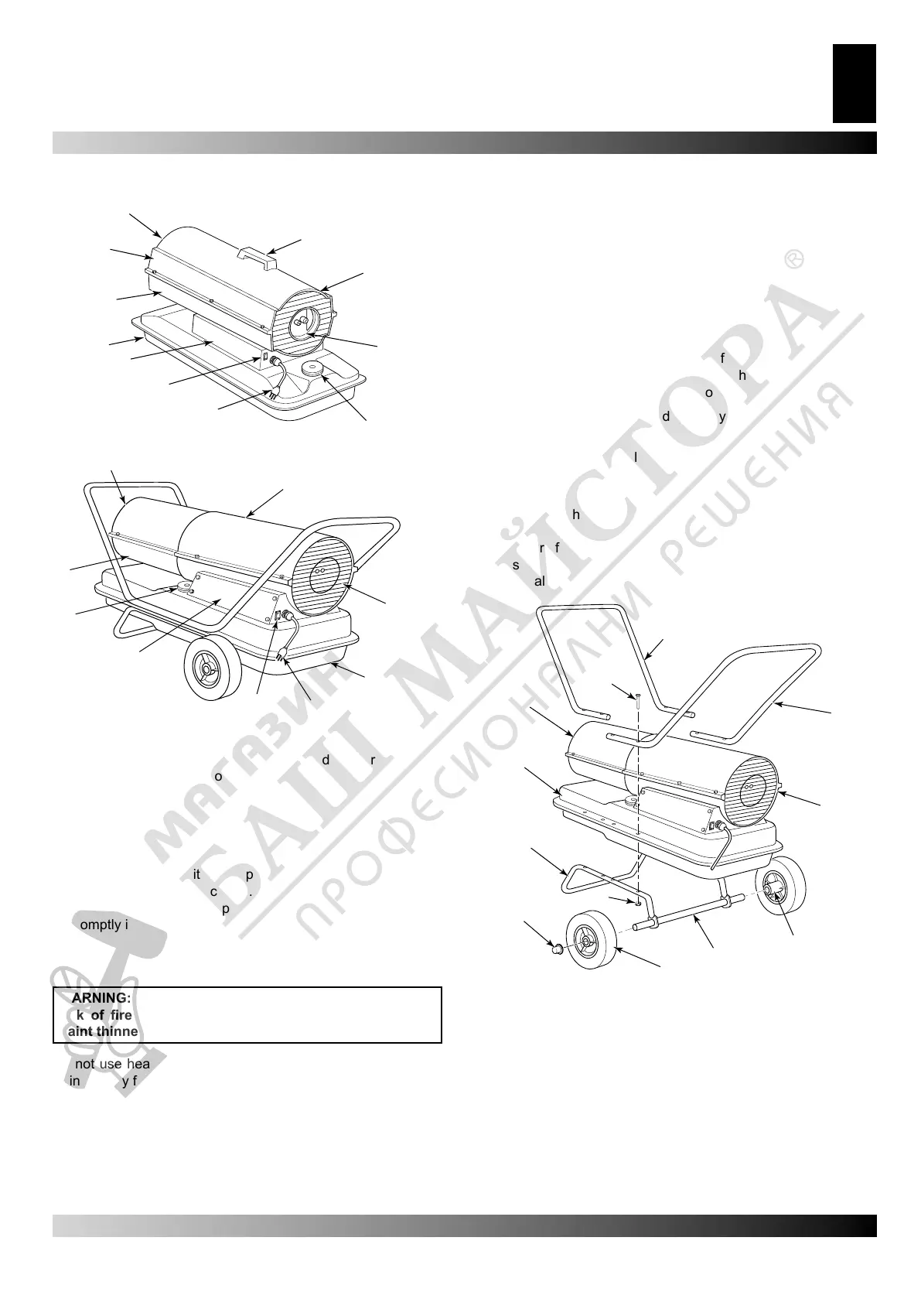
PRODUCT IDENTIFICATION
(see gure 1, e 2)
A. Hot Air Outlet, B. Handle, C. Fan Guard, D. Air Filter End
Cover, E. Fuel Cap, F. Power Cord, G. ON/OFF Switch with
Light, H. Side Cover, I. Fuel Tank, L. Lower Shell, M. Upper
Shell.
UNPACKING
1. Remove all packing items applied to heater for shipment.
2. Remove all items from carton.
3. Check items for any shipping damage. If heater is damaged,
promptly inform dealer where you bought heater.
FUELS
WARNING: Use only kerosene or No. 1 fuel oil to avoid
risk of re or explosion. Never use gasoline, naphtha,
paint thinners, alcohol or other highly ammable fuels.
Do not use heavy fuels such as No. 2 fuel oil or No. 2 Diesel.
Using heavy fuels wil result in:
• clogged fuel lter and nozzle
• use of non-toxic anti-icer in fuel during very cold weather
IMPORTANT: Use a KEROSENE ONLY container. Be sure sto-
rage container is clean. Foreign matter such as rust, dirt, or wa-
ter will cause the ame-out control to shut down heater. Foreign
matter may also require you to clean fuel system often.
ASSEMBLY
(for 100.000 and 150.000 Btu/Hr models only)
These models are furnished with wheels and handles. Wheels,
handles, and the mounting hardware are found in the shipping
carton.
Tools Needed
● Medium Phillips Screwdriver
● 3/8” Open or Adjustable Wrench
● Hammer
1.Slide axle through wheel support frame. Install wheels on
axle. IMPORTANT: When installing wheels, point extended
hub of wheels toward wheel support frame (see Figure 3).
2.Place cap nuts on axle ends. Gently tap with hammer to se-
cure.
3. Place heater on wheel support frame. Make sure air inlet end
(rear) of heater is over wheels. Line up holes on fuel tank
ange with holes on wheel support frame.
4. Place front handle and rear handle on top of fuel tank ange.
Insert screws through handles, fuel tank ange, and wheel
support frame. Attach nut nger tight after each screw is
inserted
5. After all screws are inserted, tighten nuts rmly.
A. Hot Air Outlet, B. Screw, C. Front Handle, D. Rear
Handle, E. Air Inlet, F. Extended Hub, G. Axle, H. Wheel,
I. Nut, L. Cap Nut, M. Wheel Support Frame, N. Fuel Tank
Flange.
A.
C.
E.
F.
G.
H.
I.
L.
M.
Figure 2 – Model 100.000 e 150.000 Btu/Hr
Figure 3 – Wheel and Handle Assembly.
A.
B.
C.
D.
E.
F.
G.
H.
L.
I.
N.
M.
A.
B.
C.
D.
E.
F.
G.
H.
I.
L.
M.
Figure 1 – Model 35.000, 64.000 e 70.000 Btu/Hr
PRODUCT IDENTIFICATION
UNPACKING
FUELS
ASSEMBLY