8
GB
SERVICE PROCEDURES
Continued
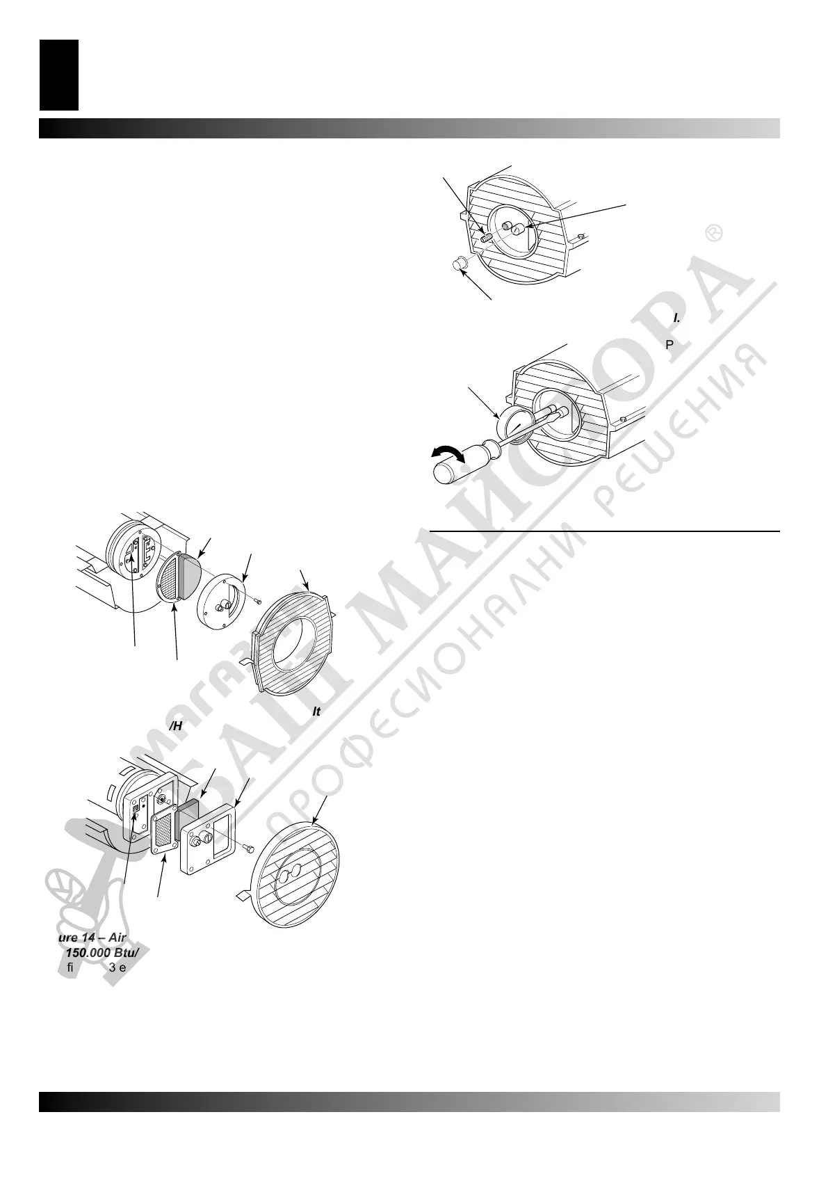
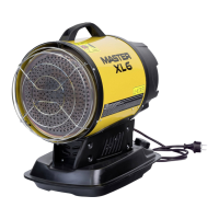
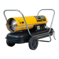
AIR OUTPUT, AIR INTAKE, AND LINT FILTERS
1. Remove upper shell (see page 6).
2. Remove lter end cover screws using 5/16” nut-driver.
3. Remove lter end cover.
4. Replace air output and lint lters.
5. Wash or replace air intake lter (see Preventative Maintenance
Schedule, page 5).
6. Replace lter end cover.
7. Replace fan guard and upper shell.
IMPORTANT: Do not oil lters.
PUMP PRESSURE ADJUSTMENT
1. Remove pressure gauge plug from lterend cover.
2. Install accessory pressure gauge (part number 4109.427).
3. Start heater (see Operation, page 4).Allow motor to reach full
speed.
4. Adjust pressure. Turn relief valve to right to increase
pressure. Turn relief valve to left to decrease pressure. See
speci cations below for correct pressure for each model.
5. Remove pressure gauge. Replace pressure gauge plug in
lter end cover.
(see gure 13 e 14)
A.Air Intake Filter, B.Filter end cover, C.fan guard
D.Air output lter, E.Lint Filter.
Model Pump pressure (Bar/PSI)
10 kW 0,207 / 3
18,5 KW 0,344 / 5
20 kW 0,344 / 5
29 kW 0,344 / 5
44 kW 0,386 / 5,6
NOZZLE ASSEMBLY
1. Remove upper shell (see page 7).
2. Remove fan (see page 11).
3. Remove fuel and air line hoses from nozzle assembly (see
Figure 17, 18 or 19).
4. Turn nozzle assembly 1/4 turn to left and pull toward motor to
remove (see Figure 20).
5. Place plastic hex-body into vise and lightly tighten.
6. Carefully remove nozzle from the nozzle adapter using 5/8”
socket wrench (see Figure 21).
7. Blow compressed air through face of nozzle. This will free any
dirt in nozzle area.
8. Inspect nozzle seal for damage.
9. Replace nozzle into nozzle adapter until nozzle seats. Tighten
1/3 turn more using 5/8” socket wrench 4.5 to 5.1 N-m (40 to
45 in-lbs). See Figure 21.
10.Attach nozzle assembly to burner strap.
11.Attach fuel and airline hoses to nozzle assembly. See Fuel
and Airline Replacement and Proper Routing see page 9.
12.Replace fan (see page 11).
13.Replace fan guard and upper shell (see page 7).
A.
B.
C.
D.
E.
Figure 13 – Air output, air intake and lint lters, 35.000,
64.000 and 70.000 Btu/Hr.
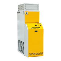
SERVICE PROCEDURES
A.
B.
C.
D.
E.
Figure 14 – Air output, air intake and lint lters, 100.000
and 150.000 Btu/Hr.
A.
B.
C.
A. Pressure gauge
Plug
B. relief Valve
C. Plastic cap
Figure 15 – Pressure Gauge Plug removal.
A.
A. Pressure gauge
Figure 16 – Adjusting pump pressure
Continued