headline bars
continuation tabs
notes
warnings
13
headline bars
continuation tabs
notes
warnings
model no. 054-6602-4 | contact us 1.800.689.9928
12
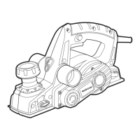
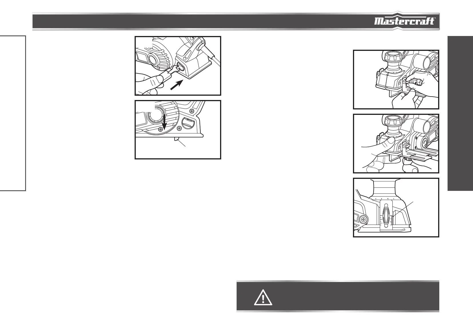
BLADE CHANGE WRENCH STORAGE
AREA
(fig 4)
Your tool is equipped with a blade wrench that is
conveniently located in the handle base where it is
always handy and unlikely to get lost or misplaced.
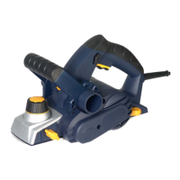
TOOL PARK REST
The park rest swings down to help keep the blade from
coming in contact with the work surface when the planer
is not in use (fig 5). The tool park rest was designed to
swing up and out of the way by itself when the back of
the planer crosses the leading edge of the workpiece.
ASSEMBLY INSTRUCTIONS
EDGE GUIDE
1. To attach the edge guide, remove the edge-guide
attachment knob and slide the edge guide into the
planer.
2. Replace the edge-guide attachment knob and firmly
tighten it (fig 6).
3. Loosen the locking nut and slide the edge guide to
the desired position. Securely tighten the locking nut
(fig 7).
RABBETTING DEPTH STOP
(fig 8)
The rabbetting depth stop allows the user to set any
rabbetting depth from 0 to 12.7 mm. For best results,
it is important that the blade be properly aligned with
the front base. The width of the rabbet is controlled by
the edge guide. The maximum cutting width is 3-1/4",
and the final depth is achieved by repeating the planing
procedure until the rabbetting depth stop contacts the
workpiece.
CAUTION!
• Always ensure that the tool is switched OFF and unplugged from the power supply before
making any adjustments and attaching accessories.
fig 6
fig 7
fig 4
fig 8
Indicator line
IMPORTANT INFORMATION
ASSEMBLY INSTRUCTIONS
fig 5
Tool park rest
 Loading...