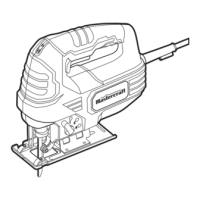
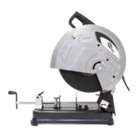
No. Description No. Description
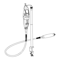
1 Carrying handle 8 Vise quick release nut
2 Lock-off button 9 Vise adjustment crank
3 Trigger switch 10 Base
4 Arbor lock 11 Depth stop screw
5 Automatic guard 12 Swing arm locking screw
6 Cut-off disc 13 Swing arm
7 Vise mitre gauge
2
3
1
4
5
6
7
8
9
10
11
12
13
KEY PARTYS DIAGRAM
SELECTING THE WORK SURFACE
It is important to place the chop saw on a
solid, at work surface that will not shift
during operation of the chop saw. Locating
the chop saw near an electrical outlet will
eliminate the need for an extension cord.
SETTING THE DEPTH STOP
The maximum cut depth is controlled by
adjusting the depth stop.
1. Lift the swing arm (1) upward as far as
it will go.
2. Loosen the depth stop lock nut (2) by
turning it counter-clockwise using a 13
mm wrench.
3. Turn the depth stop screw (3) to raise
or lower it. Adjust until the cut-off blade
enters the base slot no more than 3/16"
(5 mm) when the swing arm is fully low-
ered and contacts the top of the depth
stop screw.
4. When the depth stop screw is correctly
set, lock it in place by tightening the
lock nut clockwise.
WARNING! Always disconnect your chop saw from the power source when replacing the cut-off
disc, clamping material in the vise, adjusting the guard, cleaning or when not in use. Disconnecting the
chop saw will prevent accidental starting that could cause serious personal injury.
WARNING! Never place the chop saw near any ammable liquids or items that can be damaged by the
sparks thrown by the chop saw during cutting. The hot sparks can ignite ammable liquids.
Hot metal sparks and sharp metal pieces will damage the work surface to some degree. Make sure you
consider this fact when selecting the work surface. A non-ammable surface, such as a metal bench, will be
less likely to be damaged during cutting.
OPERATING INSTRUCTIONS
15
 Loading...