VII. Assembly and Adjustment Instructions (continued)
VIII. Operating Instructions
Removing the spur or the centre (Fig. 7)
1. Insert the push-out rod (1) into the far end
of the headstock spindle or the tailstock
spindle until it comes into contact with the
shaft of the spur or centre.
2. Tap the end of the push-out rod (1) until
the spur or centre comes loose.
12
Fig. 7
Variable speed control box
The variable speed control box contains the electrical connections to the motor. It features
three external controls: the speed control knob, the ON/OFF switch, and the circuit breaker
reset button.
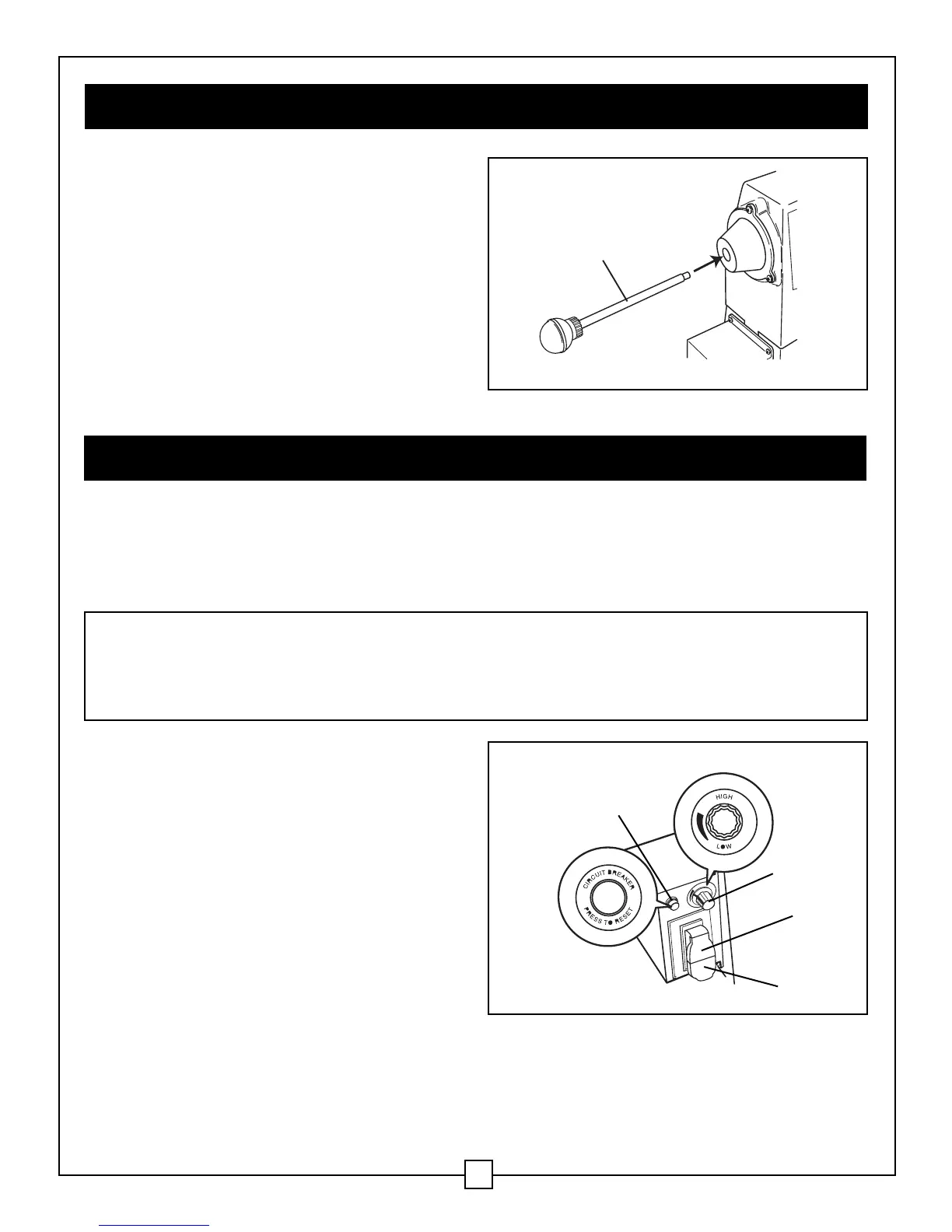
Speed control knob (Fig. 8)
The speed control knob (1) is used to set the
speed of the lathe to suit the weight of the
workpiece or the type of tool that is being
used.
1. After the lathe is started, turn the knob
clockwise in order to increase the spindle
speed (up to the maximum RPM). Turn the
knob counter-clockwise in order to
decrease the spindle speed (down to the
minimum RPM).
2. Adjust the knob until the desired rotation
speed for the workpiece is reached.
Fig. 8
3
1
4
2
WARNING: ALWAYS SET THE SPEED CONTROL KNOB TO ITS LOWEST SETTING
(COUNTER-CLOCKWISE) BEFORE STARTING THE LATHE. NEVER START THE LATHE
AT MAXIMUM SPEED. THERE IS A DELAY OF UP TO 3 SECONDS AFTER THE LATHE
IS STARTED BEFORE THE MOTOR IS ACTIVATED.
 Loading...