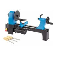
VII. Operating Instructions (continued)
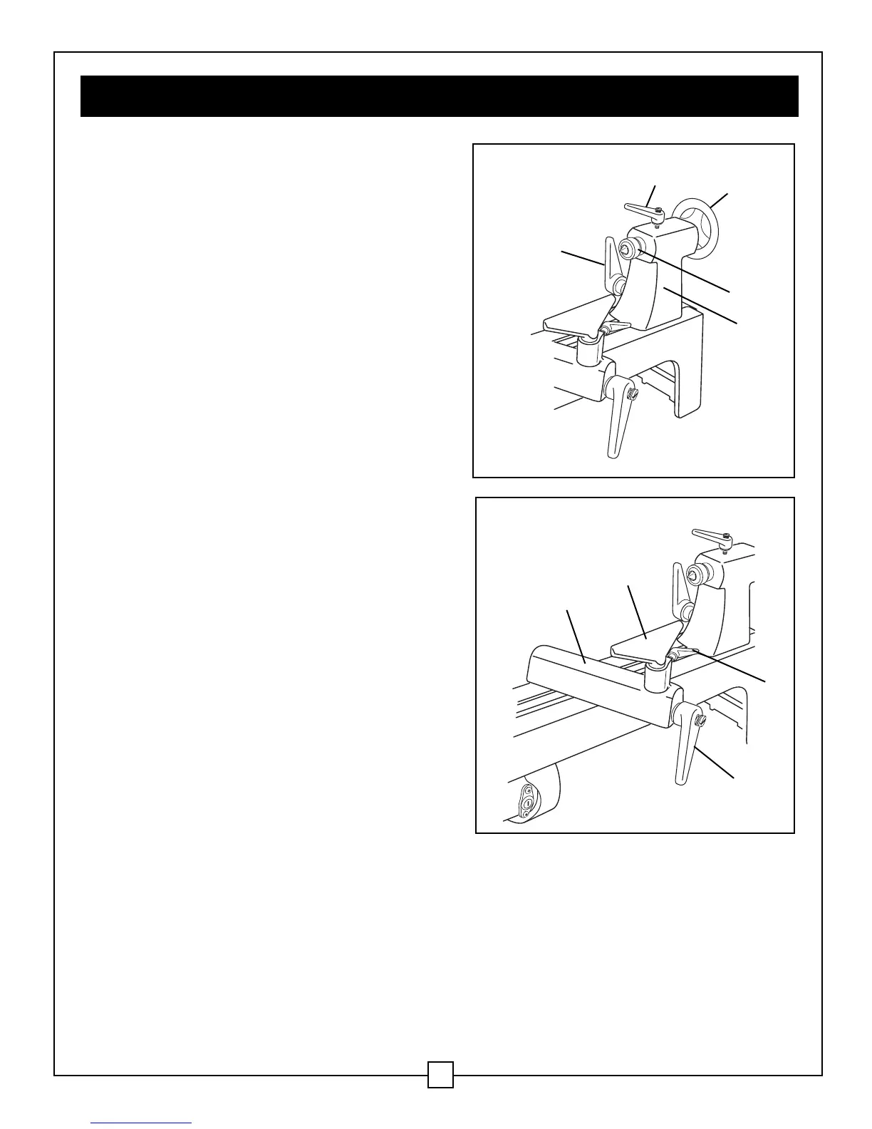
Tailstock (Fig. 9)
1. Move the tailstock (5) by loosening the lock
lever (1) and pushing the tailstock to the
desired position on the bed. Lock it in place
by tightening the lock lever (1).
2. The spindle can extend up to 2 1/2"
(6.4 cm) from the tailstock housing. Move
the tailstock spindle (4) by loosening the
spindle lock lever (2) and then turning the
hand wheel (3) clockwise in order to
extend the spindle, or turn it counter-
clockwise in order to retract the spindle.
Lock levers (1) and (2) before operating
the lathe.
3. The tailstock spindle is hollow, and can be
accessed from the handwheel end. Use the
push-out rod to remove the centre cup or
to drill holes through the centre of a
workpiece that is mounted on a faceplate.
Tool rest (Fig. 10)
1. Move the tool rest base (1) by loosening
the lock lever (4) and then moving the
base to the right or left, and back or front.
Tighten the lock lever (4) when the tool
rest base is in the desired position.
2. In order to adjust the angle of the tool
rest (2), loosen the lock lever (3), move
the tool rest to the desired position, and
then retighten the lock lever.
3. In order to change to the other tool rest,
loosen the lock lever (3) and pull the tool
rest (2) out of the tool rest base, insert the
other tool rest, adjust it to the desired
position, and then retighten the lock
lever (3).
IMPORTANT: VERIFY THAT THE TOOL REST IS ADJUSTED SO THAT IT IS AS CLOSE TO
THE WORKPIECE AS POSSIBLE. ROTATE THE WORKPIECE BY HAND IN ORDER TO
CHECK THE CLEARANCE BEFORE STARTING THE LATHE.
14
Fig. 10
1
2
3
4
Fig. 9
1
2
3
4
5
 Loading...