CONSUMER HOTLINE: 1-877-455-5508
Installation and Operation 3
The rate of flow in the discharge pipe must keep any
solids present in suspension in the fluid. To meet
minimum flow requirements (2 feet per second in
the discharge line), size the pipe as follows:
A Pipe Size Of: Will Handle a Flow Rate Of:
1 1/2" (38 mm) 12 GPM
2" (51 mm) 21 GPM
2 1/2" (64 mm) 30 GPM
3" (76 mm) 48 GPM
In a sewage system use a 2" (51 mm) check valve in
pump discharge to prevent backflow of liquid into
sump basin. The check valve should be a free flow
valve that will easily pass solids. Be sure check valve
installation complies with local codes.
In an effluent system use a 1 1/2" (38 mm) check
valve in pump discharge to prevent backflow of liq-
uid into sump basin. The check valve should be a
free flow valve that will easily pass solids. Be sure
check valve installation complies with local codes.
NOTICE: For best performance of check valve when
handling solids, do not install it with the discharge
more than 45° above the horizontal. Do not install
the check valve in a vertical position as solids may
settle in the valve and prevent it from opening on
startup.
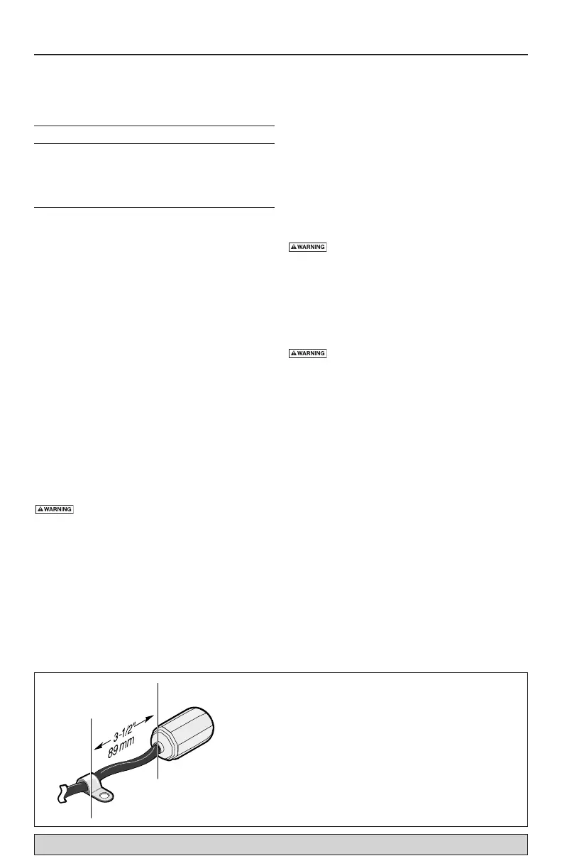
Drill a 3/16" (5 mm) hole in the discharge pipe
about 1–2" (25–51 mm) above the pump discharge
connection (but below check valve) to prevent
airlocking the pump.
Electrical
Hazardous voltage. Can shock, burn, or
kill. When installing, operating, or servicing this
pump, follow the safety instructions listed below.
1. DO NOT splice the electrical power cord.
2. DO NOT allow the electrical cord plug to be sub-
merged.
3. DO NOT use extension cords. They are a fire haz-
ard and can reduce voltage sufficiently to prevent
pumping and/or damage motor.
4. DO NOT handle or service the pump while it is
connected to the power supply.
5. DO NOT remove the grounding prong from the
plug or modify the plug. To protect against elec-
trical shock, the power cord is a three-wire con-
ductor and includes a 3-prong grounded plug.
Plug the pump into a 3-wire, grounded, ground-
ing-type receptacle. Connect the pump according
to the CEC and local codes.
For automatic operation, plug the pump into an elec-
trical outlet.
The pump is to have its own individual branch circuit
with no other outlets or equipment in the circuit. Size
fuses or circuit breakers according to the “Motor,
Switch and Cord Specifications” chart.
Risk of electrical shock and fire. Can
burn, kill or cause property damage. Make sure
that power supply information (Voltage/ Hertz/Phase)
on pump motor nameplate matches incoming power
supply exactly. Install pump according to all electrical
codes that apply.
OPERATION
Risk of fire or explosion. Can cause
severe personal injury, property damage or death.
Do not use in explosive atmospheres. Pump water
only with this pump.
NOTICE: Do not allow the pump to run dry. It will
void the warranty and may damage the pump.
An automatic reset thermal protector in the motor
will protect the motor from burning out due to over-
heating/overloading. When the motor cools down,
the thermal protector will automatically reset and
start the motor.
If the thermal protector trips frequently, check for the
cause. It could be a stuck impeller, wrong/low volt-
age, or an electrical failure in the motor. If an electri-
cal failure in the motor is suspected, replace the
pump.
The pump is permanently lubricated. No oiling or
greasing is required.