2017 OWNERS MANUAL / 184
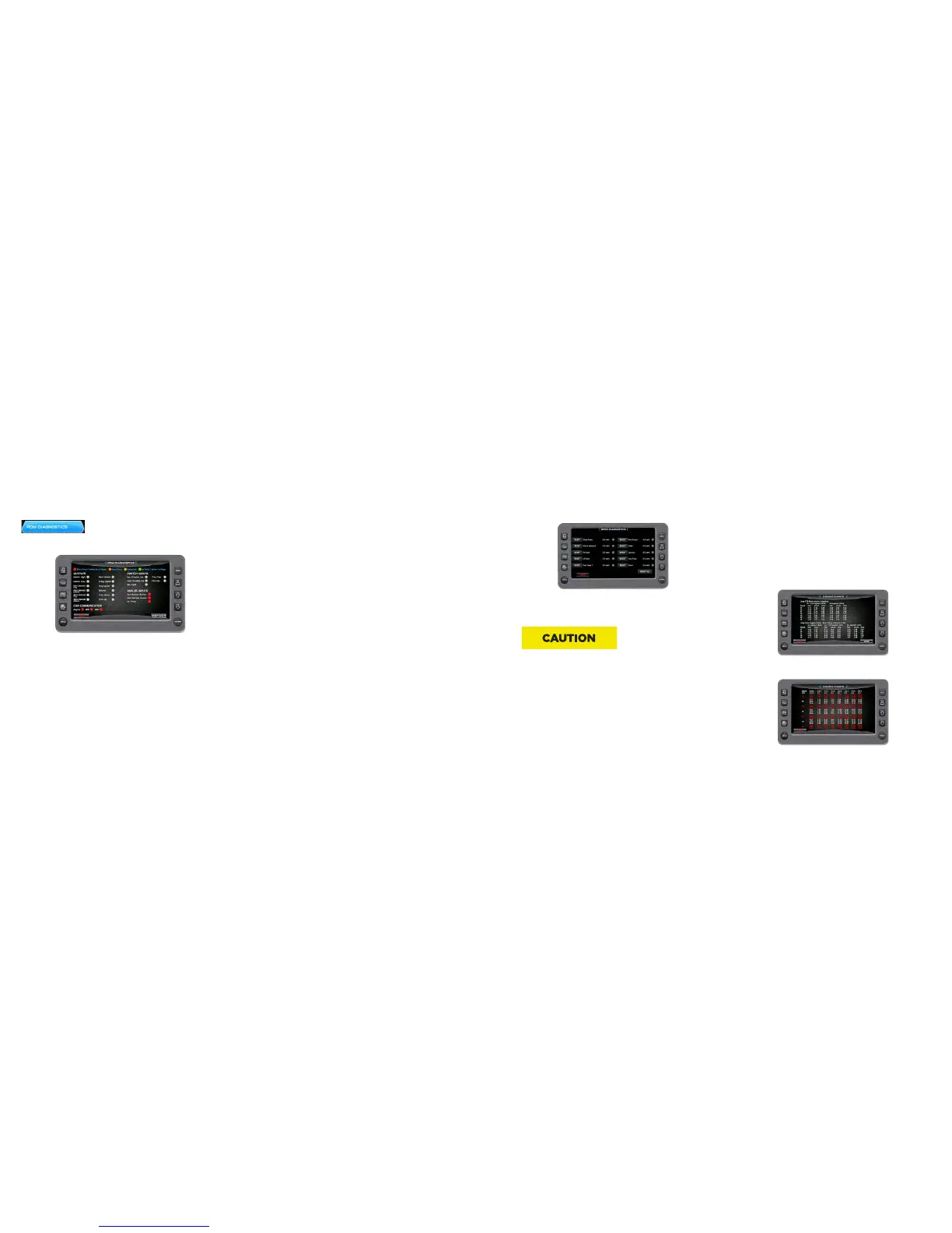
3EVENT CHARTS
On the Settings Menu screen, touch the 3 Event Touch Command to
access the 3-Event Charts screen. The charts display reference ta-
bles of the Slalom Timing Tolerances and Jump Timing Tolerances.
IMPORTANT: Use the 3-Event Charts for reference only. The charts
will not reflect any changes, should a change occur in the rule book.
We suggest periodically verifying the charts with the current rule
book. Touch [More] to view the next page.
Touch [Back] to go back one page.
Touch any Quick Access Key to exit.
To reset a tripped digital switch, press RESET next to the system
with a fault. To reset the entire EPDM, press RESET ALL on the
bottom right portion of the screen.
If a digital switch continues to trip multiple times in one outing, it is
a sign of a larger electrical issue and the boat should be taken to an
authorized MasterCraft dealer for diagnosis and repair.
The EPDM and digital switches are designed to protect the engine
and electrical system from damage. If a switch has tripped and
continues to trip even after resetting the EPDM, it may be a
symptom of a larger electrical issue, and the boat should be taken
to an authorized MasterCraft dealer for diagnosis and servicing.
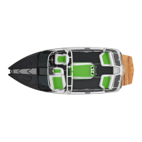
PDM DIAGNOSTICS
On the Diagnostics Menu, touch the PDM
Diagnostics touch command to access the
PDM Diagnostics screen.
EPDM & ENGINE DIAGNOSTICS
Models
All ProStar models with standard HV700 Touch Screen
Purpose
The EPDM is a solid state engine fuse block designed for all 2017
MasterCraft boats to make engine diagnostic checks easier and
more convenient for quick, on the water fixes.
Location
The EPDM screen is accessible via the HV700 Touch Screen.
To access the EPDM screen, press the Menu Quick Access key,
which will call up the settings menu. On the settings menu, tap
Diagnostics, then tap EPDM Diagnostics.
Operation
The EPDM screen displays critical engine and electrical system
operating information. Amperage draw and the status of internal
digital switches are displayed on the EPDM screen for each engine
function. Digital switch status is designated by either a green, red or
gray indicator.
• A green indicator denotes that the digital switch is functioning
properly.
• A red indicator denotes that there is a problem with the digital
switch and it has tripped.
• A gray indicator denotes that the digital switch is currently
unused or not receiving power.