Page 12
ASSEMBLY
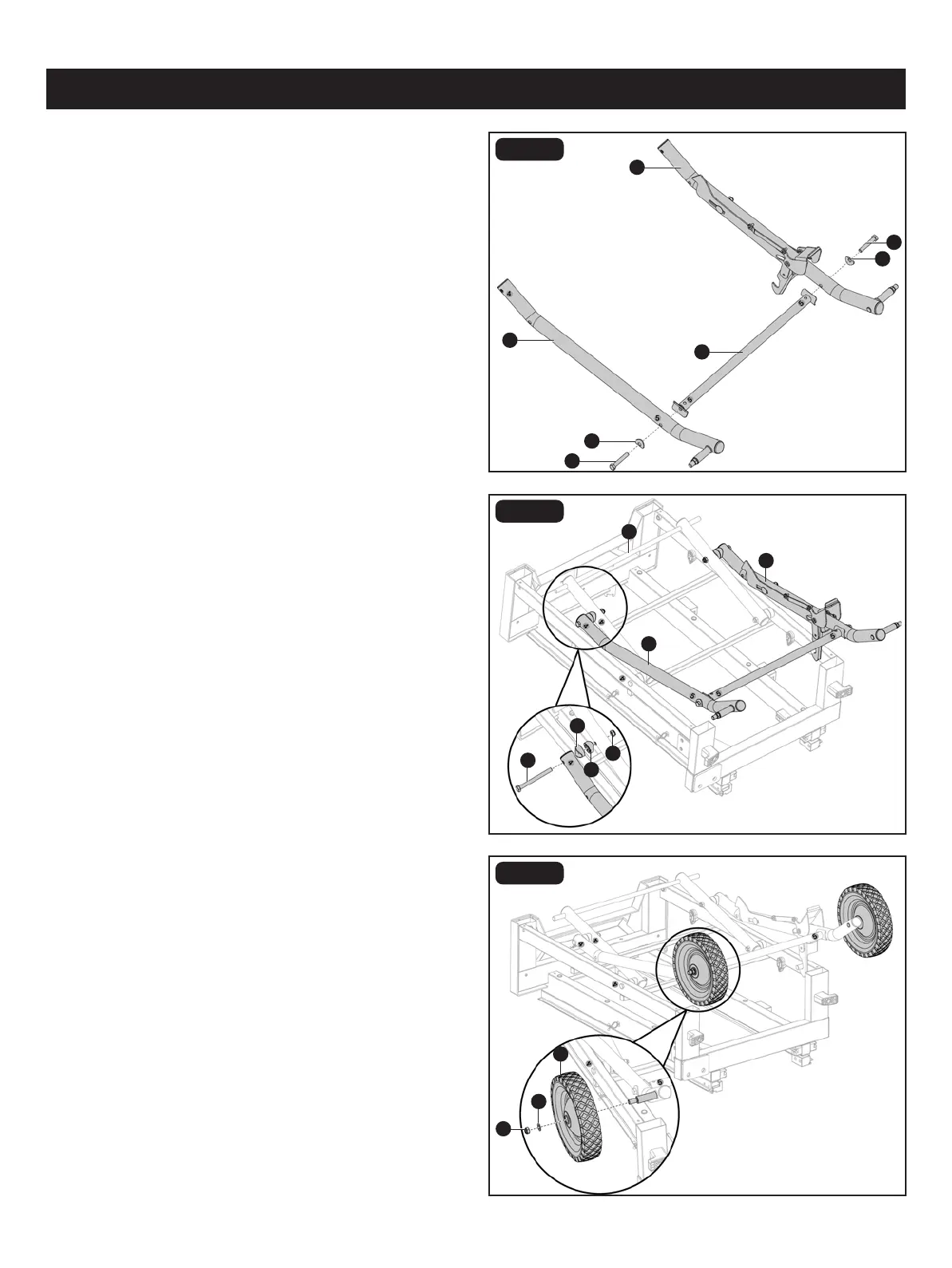
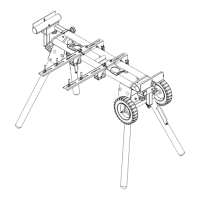
FIG. 3B
FIG. 3C
FIG. 3D
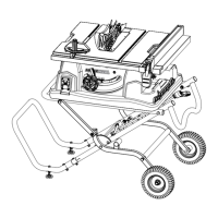
• Attach roller stand leg A (U) and roller stand leg B
(V) assembly wit upper stand assembly (R) with hex bolts
M8 x 85 (Y), spacers (W) and lock nuts M8 (Z).
• Remove lock nut M10 (GG) and at washer 10 (HH)
preassembled to roller stand leg A and roller stand leg B
from each axle.
• Slide roller wheel (FF) and at washer 10 (HH) onto axle of
rollar stand leg A. Secure with lock nut M10 (GG) . Repeat
for remaining roller wheel.
• Attach the roller stand leg A (U) and roller stand leg B (V)
with horizontal support A (AA) using curved washers (CC)
and hex bolts M8 x 50 (DD).
V
U
DD
CC
AA
HH
FF
GG
U
R
V
Y
W
W
Z
DD
CC