Page 13
ASSEMBLY
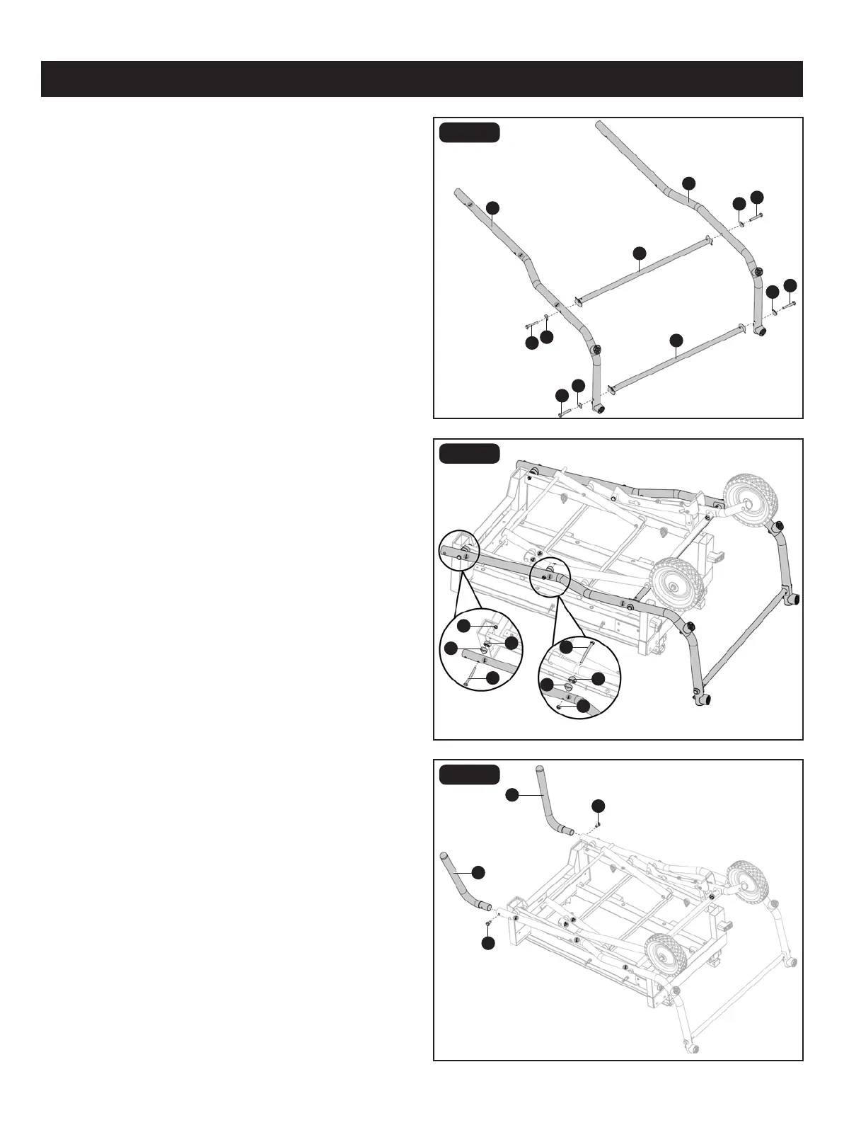
FIG. 3F
FIG. 3G
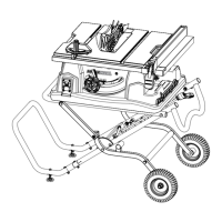
• Attach stand A and stand B assembly to the roller stand
leg A and roller stand leg B assembly, and water tray frame
assembly with hex bolts M8 x 85 (Y), at spacers (X),
spacers (W) and lock nuts M8 (Z).
• Loosen and remove hex bolt M8 x 16 (II) preassembled to
stand handle (EE).
• Attach stand handles (EE) to stand assembly. Secure with
hex bolt M8 x 16 (II).
FIG. 3E
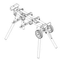
• Attach the stand leg A (S) and stand leg B (T) with two
horizontal supports B (BB) using curved washers (CC) and
hex bolts M8 x 50 (DD).
Z
X
EE
Y
W
S
T
BB
BB
DD
CC
II
DD
CC
CC
DD
DD
CC
II
Y
X
W
Z
EE