Page 15
ASSEMBLY
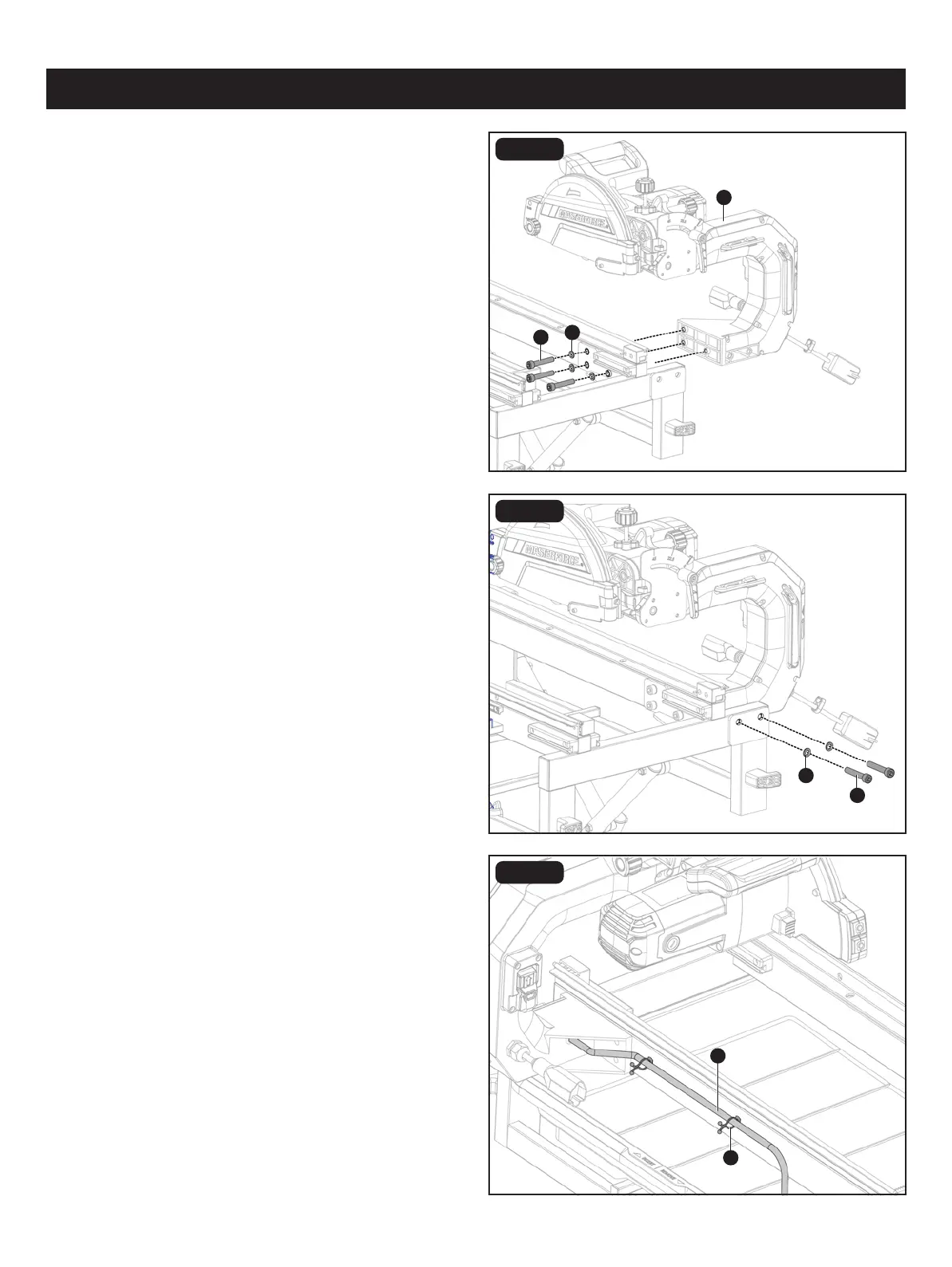
FIG. 4C
FIG. 4A
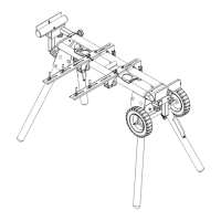
INSTALLING MOTOR HEAD TO FRAME
AND STAND ASSEMBLY (Fig. 4A-4C)
• Align holes in motor head assembly (A) with holes on side
of metal frame. Insert hex cap screws M10 x 52 (D) through
at washers 10 (C) and into motor head assembly. Secure
with 8mm hex key (supplied).
• Insert hex cap screws M10 x 52 (D) through at washers
10 (C) and into back side of frame and into holes of motor
head assembly. Secure with 8mm hex key (supplied).
• Place clear tube (KK) from motor head assembly into two
hose clamps (LL) on frame. Squeeze clamp ends together
to secure tube.
FIG. 4B
D
A
C
C
KK
LL
D