Page 16
FIG. 5
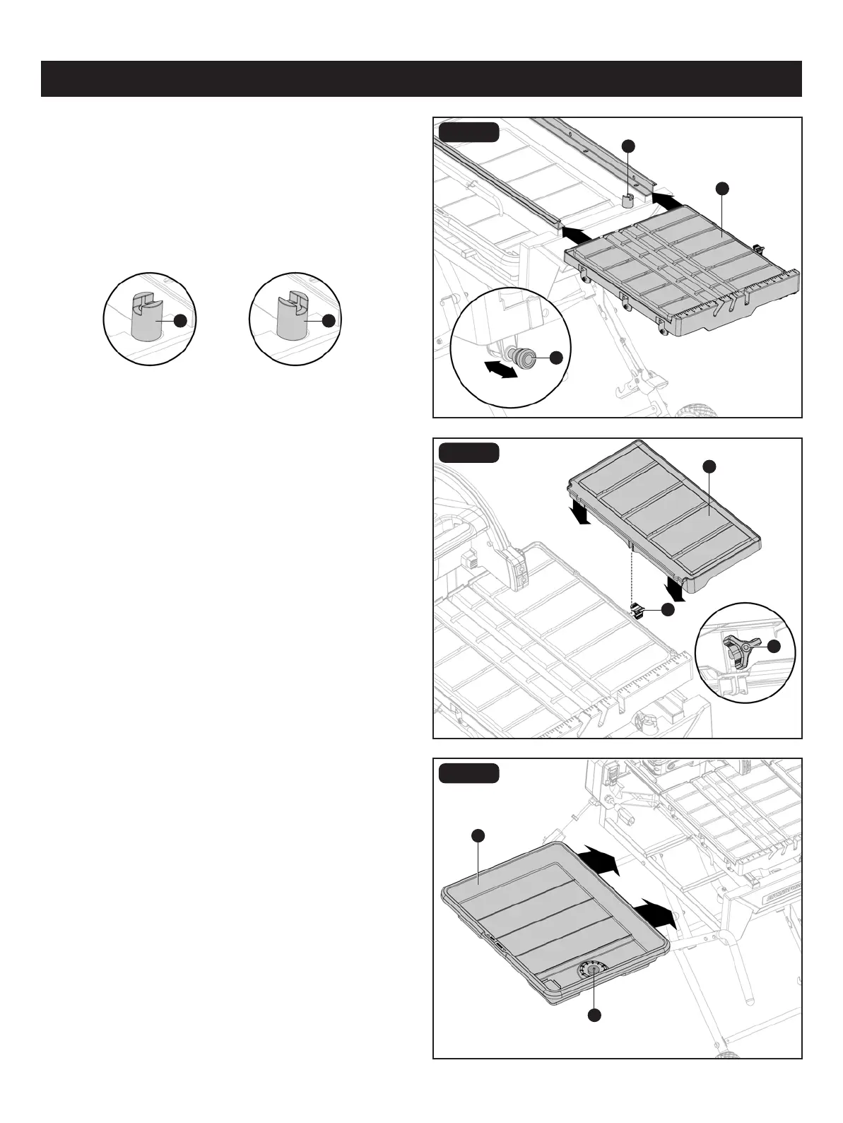
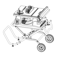
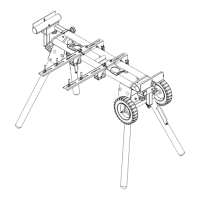
INSTALLING THE TABLE (Fig. 5)
• From right side of table (E), pull the table lock lever (MM)
out, rotate table stop (NN) to unlock position. Grasp table
(E) rmly and set rollers on rails of frame. Holding table (E)
parallel with frame, push table toward back of tile saw.
• Push table (E) along rails until nal rollers engage rails.
Rotate table stop (NN) to lock position.
ASSEMBLY
FIG. 6
FIG. 7A
INSTALLING THE EXTENSION TABLE
(Fig. 6)
• Hang the extension table (F) on the right side of the table
with the middle slot inserted into the bolt of the extension
table lock knob (OO). Tighten the lock knob underneath
the extension table clockwise to secure in place.
INSTALLING THE WATER TRAY AND
TRAY EXTENSION (Fig. 7A-7E)
• From the left side of the tile saw, place the water tray (L)
(drain plug (PP) end to the right) on the lip at the bottom
of the water tray frame.
• Slide the water tray in under the table until it hits the stops
on the other side of the frame.
NN
A
F
L
PP
To
lock
Locked Unlocked
To
unlock
NN NN
MM
OO
OO