TROUBLE SHOOTING
34 Copyright © 2008 Mastervolt / December 2008 / WHISPER 15 ULTRA - Three Phase / US
PROBLEM CAUSE SOLUTION
• Overload.
Take away the overload.
• Low level of cooling liquid or air in the
cooling system
Fill up with liquid and release air bubbles. Check
if there are air blocks in the system; refer to the
installation manual
• Water inlet system blocked.
• Broken impeller.
• Water strainer choked
• Heat exchanger choked.
Check the cooling system thoroughly.
• Broken or slipping V-belt.
Replace and adjust the V-belt tension.
Over-temperature
• Faulty thermostat
Check the thermostat or replace.
5.2.3 Warnings
Generator must be shut off immediately if:
● Motor RPM suddenly rises or drops.
● Unusual noise comes from generating set.
● Exhaust gases suddenly colour dark.
● Engine failure warning light is on
5.2.4 Service address
If you cannot correct a problem with the aid of the mal-
function table, contact your Mastervolt Service Centre or
Mastervolt Amsterdam for an extended service list, tel: INT
+31-20-3422100.
5.3 SPECIAL PROCEDURES ALTERNATOR
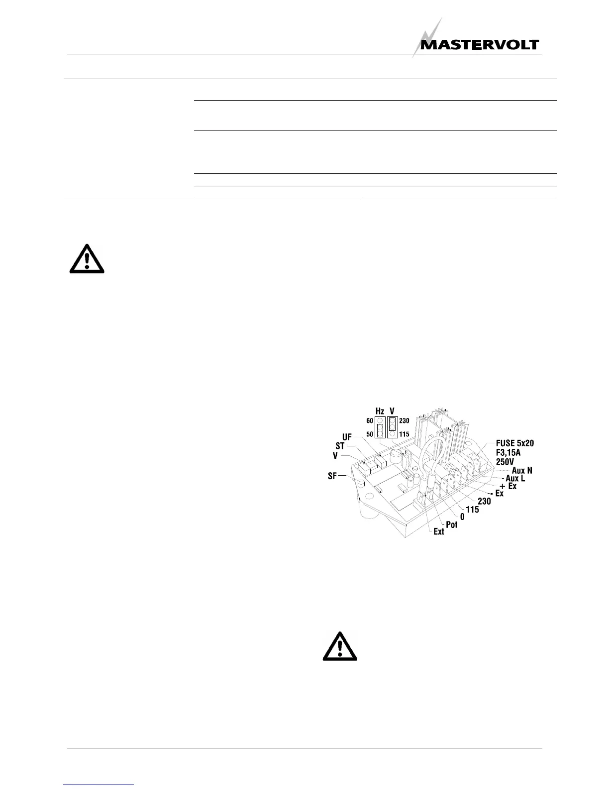
5.3.1 Automatic voltage regulator
The voltage regulator has a ±2% voltage precision in the
machine working range with distortion free loads.
The phase voltage can be adjusted by trimmer “V” (see
figure 24) from 100V to 140V (@120V nominal voltage
between phase and neutral) or 200 to 280 (@208V
nominal voltage between two phases when wired as three
phase).
The regulator is equipped with a frequency dependant
excitation limiter; the frequency can be calibrated by
trimmer “UF”, which is factory set at 56Hz @ 60Hz
nominal (46Hz @ 50Hz nominal), ±1Hz. On reaching this
frequency, the machine begins to reduce its voltage until it
deactivates for very low frequencies.
A fuse protects the regulator and generator against
overloads and/or faults; a pocket has been provided on the
edge of the board to hold a spare fuse (rapid type 32x6.3
2A).
Another trimmer “ST” allows to adapt the regulator to the
generator parameters.
The regulator has been built to suppress the voltage
surges on releasing the load that are below 20% at
nominal load.
AVR SETTINGS
To select the AVR settings access the control board after
removing the cover. Most adjustments are factory set to
ensure satisfactory results in the operating tests on
commissioning. Further adjustments may be necessary to
ensure optimum operation under specific working
conditions.
If the alternator has to operate at 60Hz the jumper “J”
should be placed across the terminals marked “60Hz”, if it
has to operate at 50Hz this jumper must be placed across
the terminals marked “50Hz”
The output voltage can be changed by adjusting
potentiometer “V”. Take the generating set to its nominal
speed and turn until the required voltage is obtained.
Fig. 22. Automatic Voltage Regulator (AVR)
Setting the bottom speed at 60 (50)Hz: start up rotation of
the generating set adjusting it to obtain a frequency of 56
(46)Hz. Turn trimmer “UF” until the voltage begins to
drop. Restore nominal speed.
CAUTION
If the bottom speed is set at too low a
frequency the generator may be damaged. On
the other hand, too high a frequency can
cause voltage drops with high load.
 Loading...


