OPERATION
10 Copyright © 2009 Mastervolt / December 2009 / WHISPER 3.5 / EN
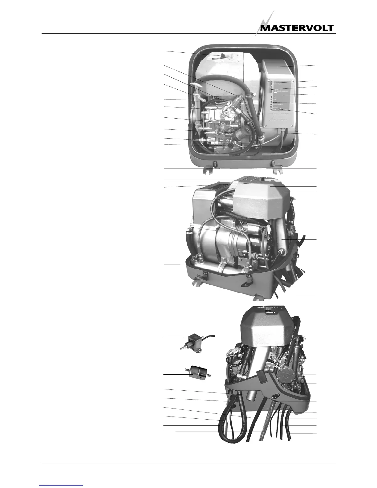
2.4 COMPONENTS
2.4.1 Main components to identify
1 Air inlet (bottom side);
2 Starter motor;
3 Battery connection (positive);
4 Battery connection (negative);
5 AC 230 V wiring;
6 MasterBus communication ports;
7 Fuel filter;
8 Fuel pipe inlet;
9 Fuel pipe return;
10 Bypass hose air vent;
11 Cooling water in;
12 Exhaust manifold (water cooled);
13 Thermo-switch exhaust;
14 Glow plug;
15 Injector;
16 Valve cover;
17 Decompression handle;
18 Oil filler cap;
19 Solenoid fuel valve;
20 Electric fuel lift pump;
21 Cooling water pump;
22 Oil pressure pump;
23 Fuel pressure pump
24 Oil pressure switch;
25 Oil sump pump;
26 Exhaust connection;
27 Fuel return;
28 Oil filler cap/ oil level indicator;
29 Digital Diesel Control Panel + local control panel;
30 Top cover plate connection box
31 Fuse 1;
32 Fuse 2;
33 Remote control cable;
34 Stop solenoid;
35 Oil strainer cover;
36 Start / Stop button;
37 Status LED’s
38 RPM set screw;
39 Oil temp switch;
40 Plug screw;
41 Heat exchanger.
Figure 2: Overview Whisper 3.5.
18
19
27
25
40
23
38
30
29
31
32
36
34
24
28
1
39
14
2
41
20
7
26
3
9
4
10
11
1
17
15
16
12
13
3
4
21
22
35
33
20
5
8
37
6
 Loading...


