INFORMATION
10 July 2009 / WHISPER 6/8/11 / US / Copyright © 2009 Mastervolt
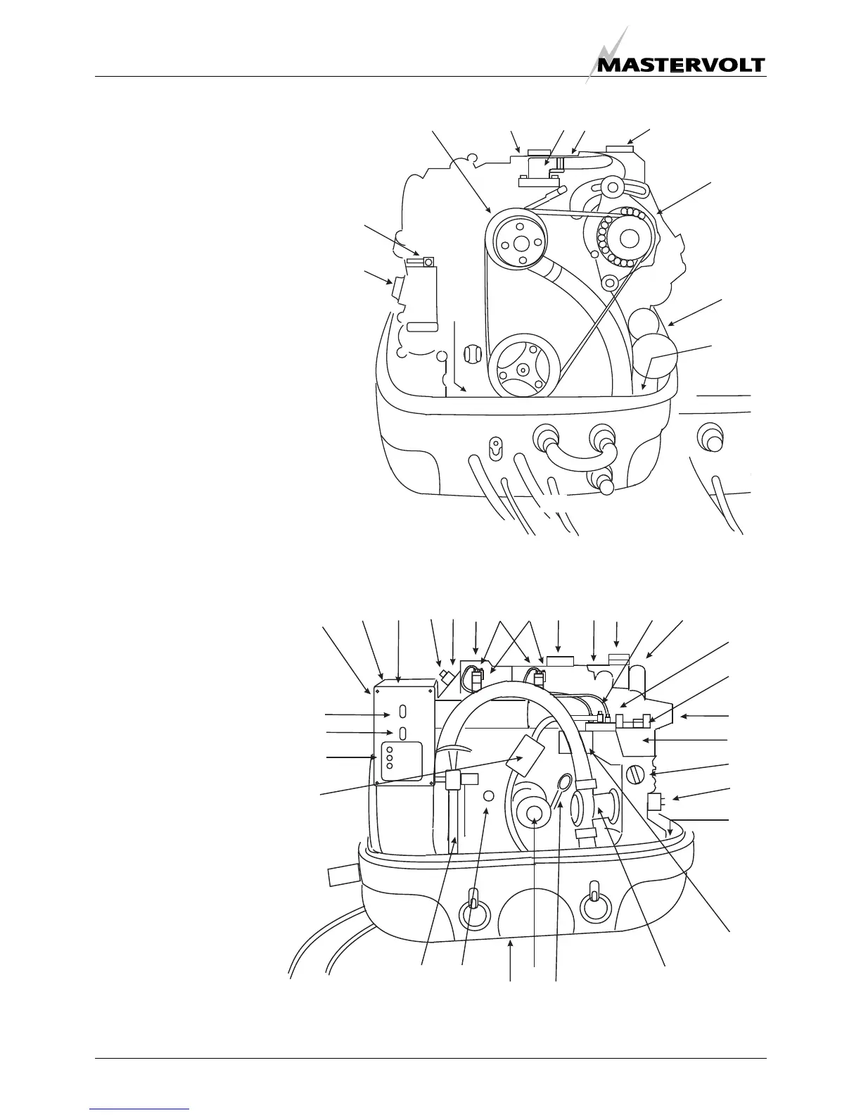
2.4 COMPONENTS
2.4.1 Main components to identify
1 Air inlet;
2 Starter motor;
3 Battery connection ( negative);
4 Battery connection ( positive);
5 AC 120/240V wiring;
6 AC 120/240V output connection box;
7 Fuel filter;
8 Fuel pipe inlet;
9 Fuel pipe return;
10 Bypass hose air vent;
11 Cooling water in;
12 Exhaust manifold (water cooled);
13 Thermo-switch exhaust;
14 Injector (Wh 6/8)2x (Wh11 3x);
15 Glow plug (Wh 6/8)2x (Wh11 3x);
16 Valve cover;
17 Circulation pump;
18 Filling cap oil 2x;
19 Solenoid;
20 Electric fuel lift pump;
21 Raw water pump;
22 Cooling liquid temperature switch;
23 Fuel pressure pump
24 Oil pressure switch;
25 Oil sump pump;
26 Exhaust connection;
27 Fuel vent screw;
28 Oil level indicator;
29 Control panel;
30 Capacitors (optional voltage
regulator for Whisper 8/11);
31 Fuse 1;
32 Fuse 2;
33 Remote control cable;
34 Cooling water injection;
35 RPM adjustment screw;
36 Thermostat housing;
37 Alternator;
38 Filling cap coolant;
39 Heat exchanger;
40 Drain plug coolant;
41 Stop lever;
42 Oil filter;
43 Digital Diesel Control unit.
Fig. 2: Overview Whisper 6/8/11
2
3
4
8
9
10
18
1617 36 22 38
37
11
20
24
18
35
39
11