TROUBLE SHOOTING
US / WHISPER 6/8/11 / July 2009 / Copyright © 2009 Mastervolt 33
5.4.2 Adjusting valve clearance and
retightening the cylinder head bolts.
Both procedures have to be carried out with a cold engine.
When both procedures are carried out be sure to retighten
the cylinder head bolts before adjusting the valve
clearance. When retightening the cylinder head bolts,
drain the coolant by removing the drain plug (ref. to fig. 2).
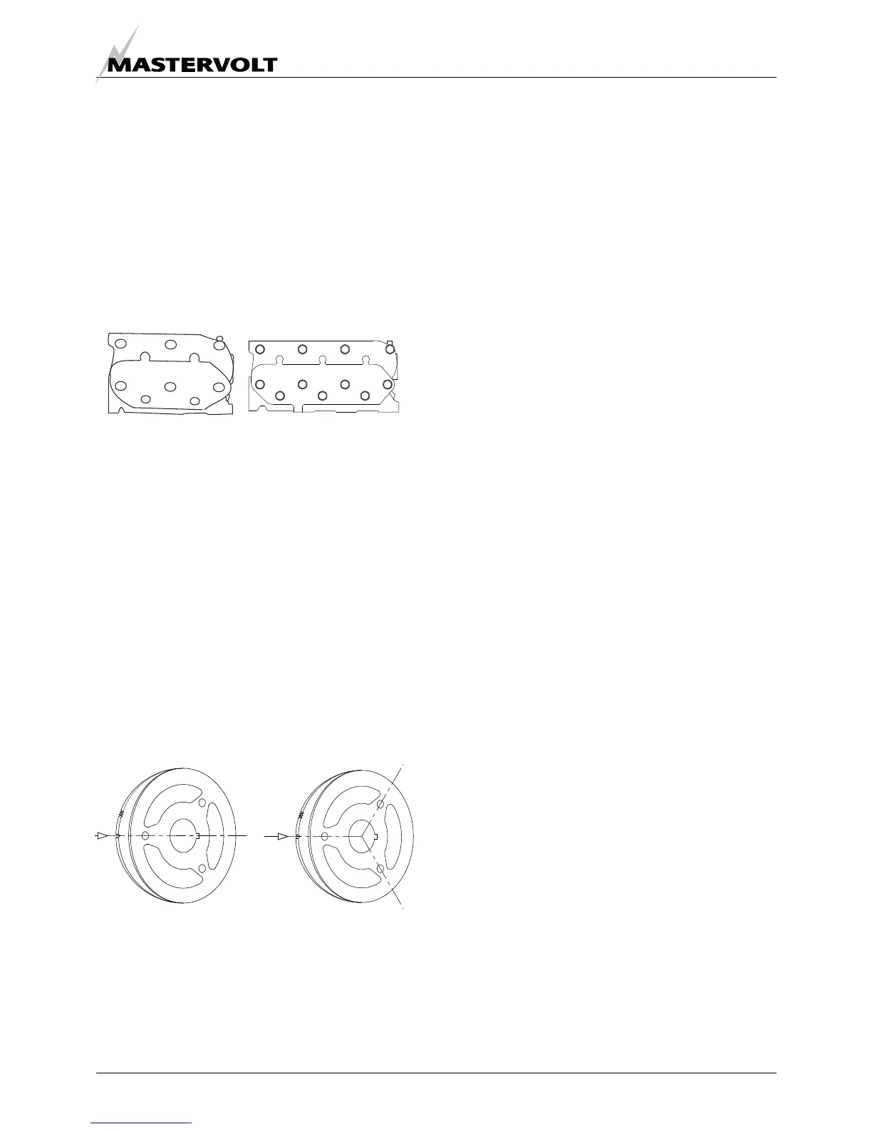
Loosen the bolts slightly, remove the rocker assembly (the
rocker arms, shaft, and stays) and then retighten the bolts
to the specified torque in the numerical order illustrated
(ref. to fig. 18).
Tightening torque: M10 bolts : 54-61 Lb-ft (75-85 Nm)
M8 bolts: 14-21 Lb-ft (20-30 Nm)
Rocker stay tightening torque:
M8 bolts: 11-15Lb-ft (15-22 Nm)
The clearance of both (intake and exhaust) valves should
be 0.01 inch (0.25 mm) in cold condition.
1 Set the piston of the first cylinder to be adjusted to top
dead centre (T.D.C.) of compression stroke.
2 The T.D.C. of compression stroke can be found by
aligning the T.D.C. mark (notch) on the crankshaft
pulley with the mark on the gear case (ref. to fig. 20).
3 First align the T.D.C. mark for the No. 1 cylinder.
Confirm that the valves do not move up or down when
the crankshaft is turned about 20 degrees in normal
and reverse direction of rotation. If the rocker arms
move piston no.1 is on the T.D.C. of the intake or
exhaust stroke. In such case turn the crankshaft 360°
in the direction of engine rotation again. No. 1 piston
is now at T.D.C. of the compression stroke.
4 To adjust the valve clearance of the No. 2 and No.3
cylinder
a. Two cylinder engine (Whisper 6 and 8): the
crankshaft pulley has to be turned 180 degrees
clockwise to set this piston to T.D.C.
Adjustment can be executed.
b. Three cylinder engine (Whisper 11): After
adjusting the valves of cylinder 1 turn the
crankshaft 240 degrees clockwise from the
T.D.C of cylinder 1 to the T.D.C of cylinder 3.
Position 2 fig. 19b against the notch. Adjust the
valves of cylinder 3. Then turn the crankshaft
240 degrees further clockwise to the T.D.C of
cylinder 2 and adjust the valves; position 3 fig.
19b against the notch.
Check after each adjustment that the valves do not move
up and down when turning the crank craft about 20
degrees clockwise and counter clockwise of T.D.C.
6
3
5
7
4
2
8
1
11 7 5
10
946
213
8
Fig 18a
Whisper 6/8
Fig 18b
Whisper 11
Fig. 19a:
2 cylinder engine
1
2
1
2
3
Fig. 19b:
3 cylinder engine