11
Modbus is a serial communications protocol originally designed for use PLCs. Simple and robust, it has since become
one of the de facto standard communications protocols in the industry, and it is now amongst the most commonly
available means of connecting industrial electronic and control devices.
MODBUS COMMUNICATIONS
2.1 Modbus Settings
In order to reduce unnecessary complexity, the system is compatible with with the BASIC Modbus implementation class
with some additional features, as detailed in the following table. All settings have a default which is valid until the
operator changes them via the conguration menu.
Setting Implemented Default
Address Congurable from 1 to 247 1
Baud Rate 9600, 19200 19200
Parity Even,Odd None Even
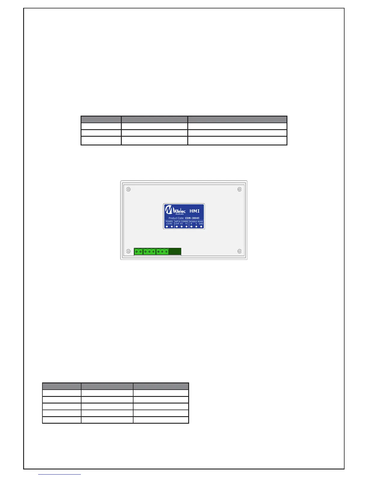
2.2 Modbus Physical Connection
2.3 Modbus Poll and Timeout Settings
The poll rate is how often the Modbus master requests information from the slave. Since the processor on the HMI
must also operate the user interface and continually operate the communication link with the connected controller, it is
only able to cope with a limited number of Modbus transactions per second. The recommended maximum poll period of
500ms (2 polls per second), however a period of 1 second is preferred. Periods as low as 250ms can be achieved but
there can be no guarantee as to the HMI’s ability to respond at this rate (particularly with write commands).
Certain Modbus operations require the HMI to initiate further communications with the attached controller and this can
take signicantly more time than other operations for the controller to respond. For this reason a timeout period of no
less than 1000ms should be used. If the Modbus connection is being used for monitoring only (rather than monitoring
and control) then the timeout can be reduced to 500ms.
2.4 Modbus Supported Function Codes
The Modbus protocol uses function codes to perform actions such as reading and writing the dierent physical data
types. Only a portion of the full range of function codes is used, as outlined in the following table:
Function Code Description Valid Address Ranges
01 Read coils 1 to 8, 17 to 24, 33 to 38
03 Read holding registers 1 to 3, 17 to 46, 65 to 78
05 Write single coil 49, 65
06 Write single register 65 to 78 *
16 Write multiple registers 65 to 78 *
* Address ranges marked with an asterisk can only be written to with the value 0x0000 for logged data or 0x0000 to
0x0002 for pump modes.
The HMI provides a three pin pluggable terminal for connection of the three RS-485 connections required for the
Modbus interface: A, B and GND. As with the other HMI connections the wiring information is printed on the rear label of
the unit.
 Loading...