Rev. Descrizione Redatto/Gestito Approvato Cod.Ident. Pagine Data Em.
03 Manuale Istruzioni Ufficio Tecnico Resp.Tecnico C314.M01.EN.03
6/18
03/2009
6
DANGER
Connect the ground by the terminal PE (yellow-green) before making any other connections.
DANGER
Apply a knife switch at the top of the connecting cable of the machine to the power system.
The knife switch must be combined with a safety device against the overload with a differential switch
(safety switch).
The technical features of the safety device must be in accordance with the standards in force in the
country where the machine has been installed.
ELECTRIC TOLERANCES:
• Real voltage ± 10 % of the nominal one
• Frequency: ± 1 % of the nominal one in a continuous way ± 2 % of the nominal one for a short period
• The harmonic distortion of the sum from the second to the fifth harmonics not more than 10 % of the total voltage as a
real value between the conductors. A further distortion of 2% is accepted for the sum from the sixth to the thirtieth
harmonics of the real total value between the conductors.
• With reference to the tension unbalance of the three-phase voltage, the inverted sequence component and the zero
sequence component must not be more than 2% of the direct sequence component of the voltage
• The voltage pulses must not last more than 1,5 ms with an up/down time between 500 ms and 500 μs and a peak
value not higher than 200 % of the real value of the nominal tension.
• The electric feeding must not be interrupted or zeroed for more than 3 ms. Between two interruptions it must not take
more than 1 s.
• The interruptions must not overcome 20 % of the tension peak for more than one cycle. Between two interruptions it
must not take more than 1 s.
The manufacturer assumes no liability for any damages to people, things and animals caused by the non-compliance of
the above instructions.
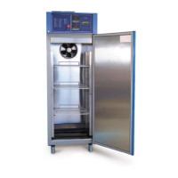
Chapter 4 MACHINE FEATURES
4.1 FEATURES OF THE APPLIANCE
Model C314 C315
Capacity 520 1200
Temperature range
-20 °C +60°C
Environment
temperature
+10 °C - +60°C
Type of gas R 404 A
4.2 CALIBRATION
The machine is controlled and calibrated by the manufacturer, using sampling tools, which are periodically checked by
Official Institutions.
WARNING
Laws now in force foresee the calibration checking after every machine lifting.
Once the machine is installed and ready to work, Official Institutions must check the calibration before
this can be used for official tests.
Chapter 5 OPERATOR INTERFACE
5.1 CONTROLS AND MESSAGES
A
Main switch – Emergency push-button
I
Hot Signal lamp
B
Ventilation push-button
L
Dry Signal lamp
C
Temperature push-button
M
Moisture Signal lamp
D
Climax push-button
N
Motor contactors Signal lamp
E
Inside light push-button
O
Temperature alarm Signal lamp
F
Push-button to turn off sound alarms
P
Water alarm Signal lamp
G
Main supply Signal lamp
Q
Temperature regulator
H
Cold Signal lamp
R
Humidity regulator
A
Main switch – Emergency push-button
 Loading...