24
CHAPTER 8: PART REPLACEMENT GUIDE
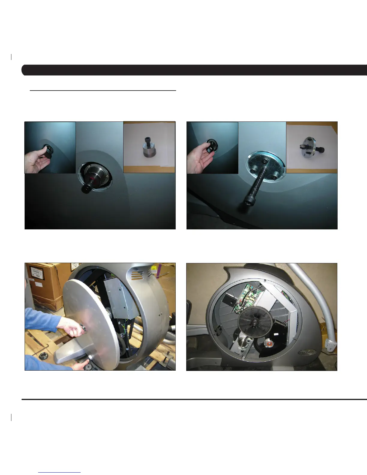
8.1 FRONT DISK REPLACEMENT - CONTINUED
FIGURE H FIGURE I
FIGURE J
FIGURE K
7) Thread the Matrix disk removal tool into the center hub (Figures H and I). Note: There are two different removal tools. If you have 3
tapped holes on your center hub see Figure I, if the inside of the hub
is tapped (no holes) see Figure H.
8) Turn the center bolt of the removal tool clockwise until the main disk can be removed (Figures J and K). Repeat if necessary for the opposite
side disk.
9) Reverse Steps 1-8 to install a new front disk. note: When reinstalling the 24mm nut, it should be tightened to 196 N-m Torque.