8
For Vega FOT only Power Supply Cable and Ethernet Cable with
RJ45 Plug will be provided.
What your package contains
Things you will need
Installation Instructions
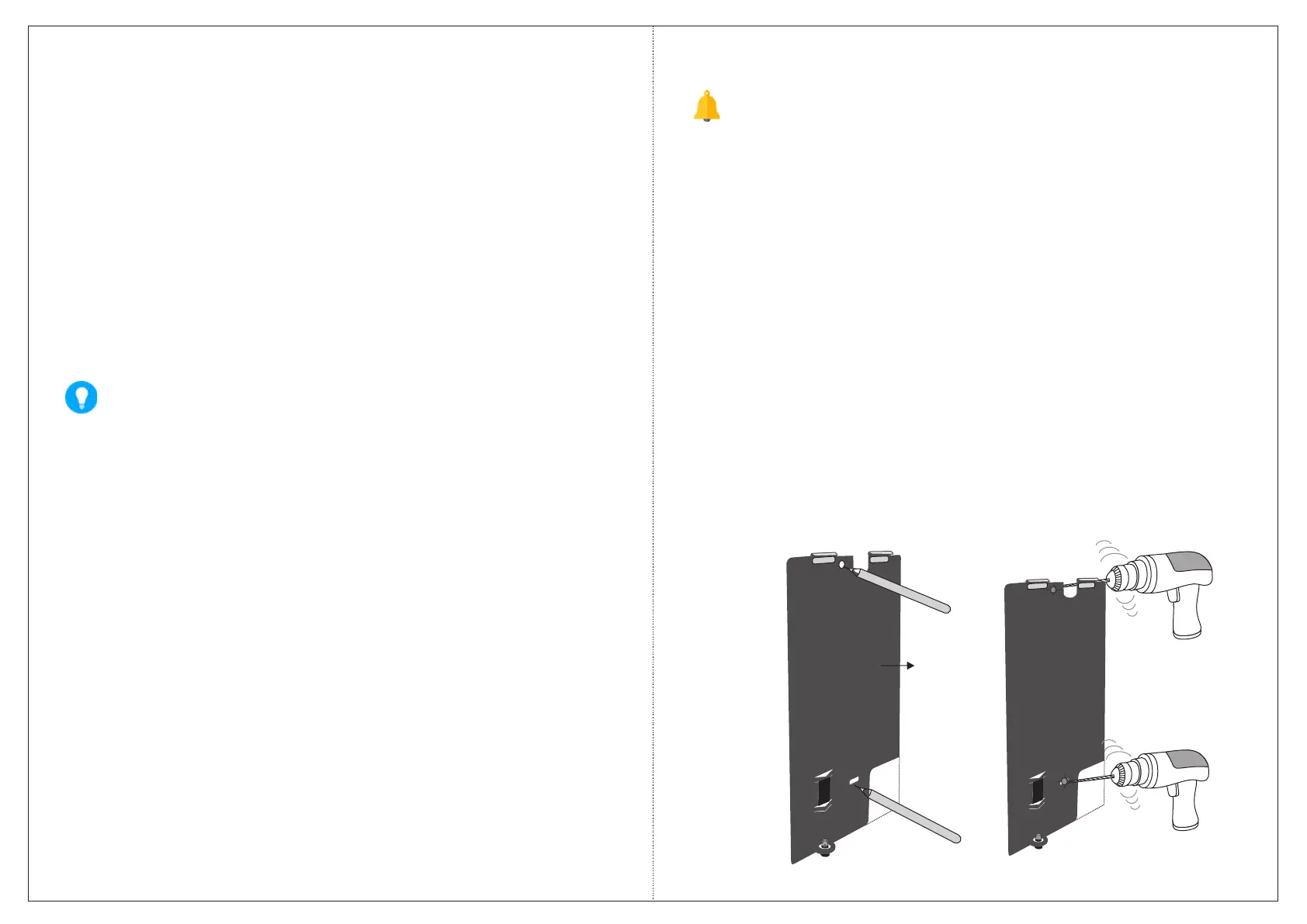
Step 1: Trace screw holes A and B on Mounting Plate. If required,
trace out rectangular opening C also. Drill screw holes along the
traced markings.
B
A
C
Mounting
Plate
B
A
C
• COSEC VEGA Controller Unit
• Mounting Plate with screw
M3/6
• 2 Screws M5/25
• 2 Screw Grips
• Power Supply Cable (with DC
Jack)
• Power Adpater 12VDC,2A
• Exit Switch Cable
• EM Lock Cable
• Ethernet Cable with RJ45 Plug
• Auxiliary I/O Cable
• A Power Drill
• A Wire Stripper
• A Screw Driver Set
• Insulation Tape
• Access to COSEC Server application to configure COSEC
Vega.
• A Stand-alone computer with a Web-browser to change the
network settings of COSEC Vega.
• Installation and servicing should be done only by a qualified
technician.
• There are no user-serviceable parts inside.
• Opening or removing the device cover may result in electric
shock or exposure to other hazards.
• Use this product only for the purpose for which it was
designed.
Figure 9
7
 Loading...