www.szmatrix.com
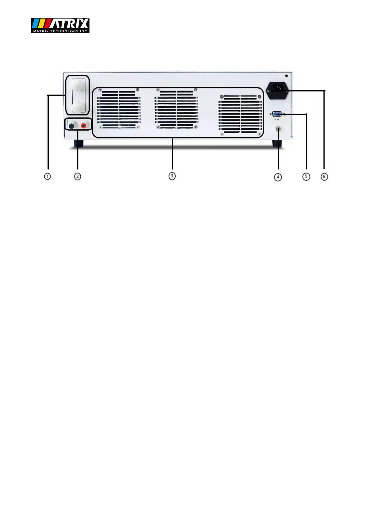
The rear panel layout of the programmable DC power supply is shown in the following figure.
Figure 3.2 Programmable DC Power Rear Panel
① Output terminal,
② Voltage compensation terminal
③ Heat dissipation hole
④ Ground terminal
⑤ RS-232 communication interface
⑥ Power input socket
3.2 Pre-check
Please follow the steps below to check the power supply to make sure the power supply is working properly.
1. Inspection
Please check whether you have received the following accessories when you receive the power supply. If there
is any missing, please contact your nearest dealer.
□ A power cord (conforming to the voltage standard used in the region)
□ An operation manual (standard)
□ One communication cable (standard)
 Loading...