21
9.4 TENSION REPLACEMENT - CONTINUED
CHAPTER 10: PARTS REPLACEMENT GUIDE
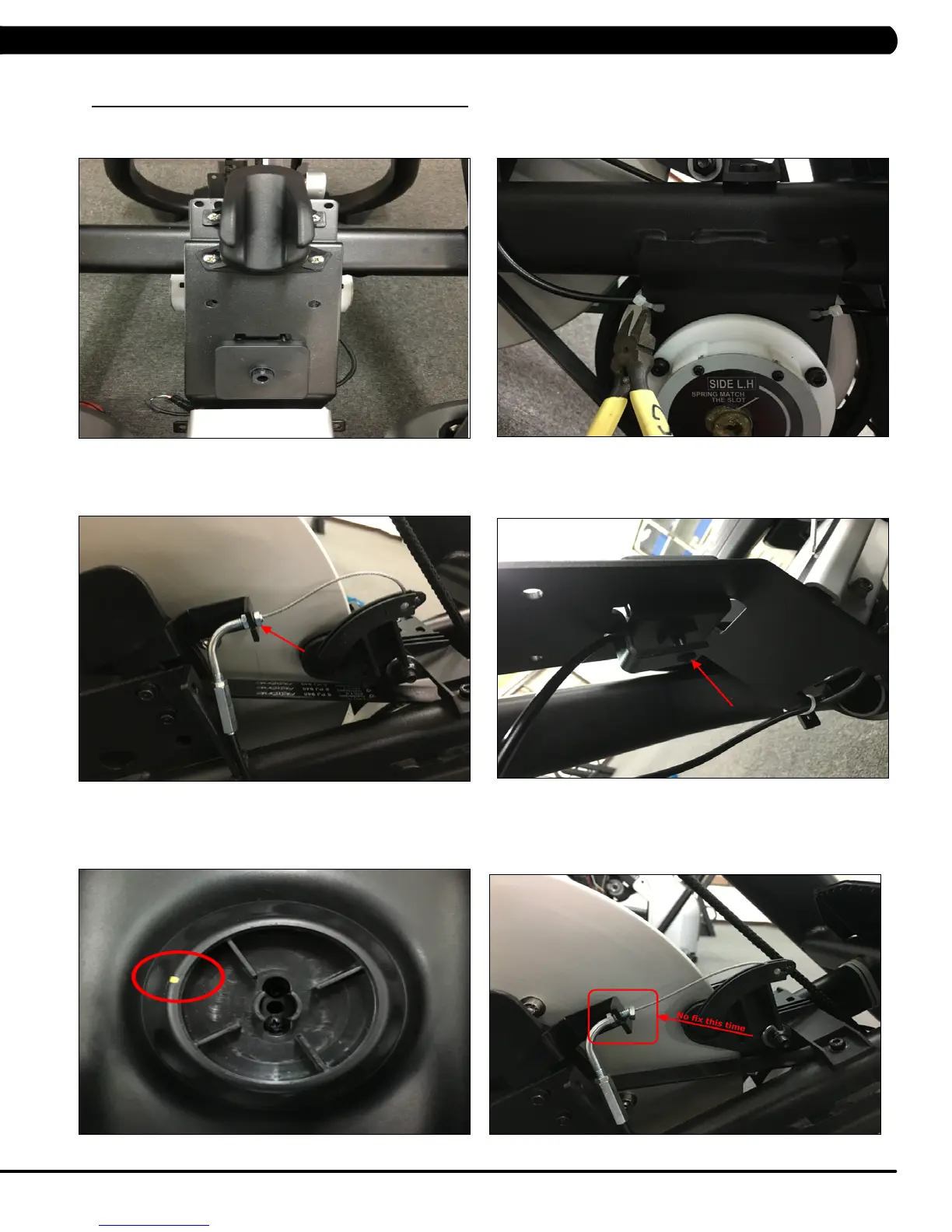
6) Remove the 4 screws holding front frame cover to the frame (Figure E).
7) Cut off the 2 cable tie (Figure F).
8) Remove the tension wire (Figure G).
9) Remove the one screw holding tension wire to the frame (Figure H).
10) When reinstalling the tension knob, please make sure the yellow mark at the left side (Figure I).
11) Install the tension wire (Figure J). Note: Don’t fix the tension wire to the frame at this time.
FIGURE H
FIGURE E
FIGURE F
FIGURE G
FIGURE JFIGURE I
 Loading...