−2−
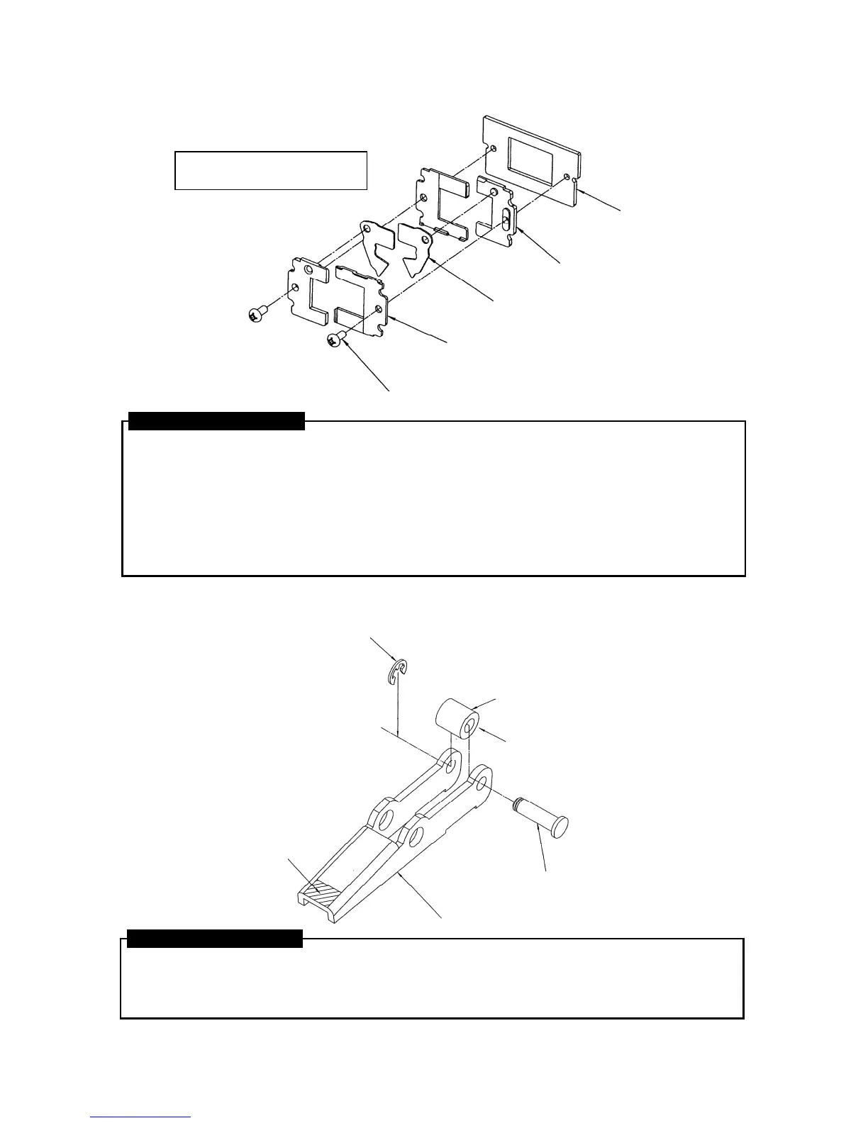
1. CLINCHER ASSY.
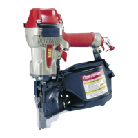
2. CLINCHER LINK ASSY.
1. Matching the hole on the upper part of the Clincher with the projection on the upper part of the
Clincher Holder CF, place the two pieces together. Make two assemblies in the same way.
2. Setting the assemblies so that the Clincher side is facing upwards, place the Clincher Sub-holder CF
on top, matching the screw holes with those of the Clincher Holder CF. Make two assemblies in the
same way.
3. As shown in the diagram, place the assemblies produced in part 2 on top of the Clincher Holder
Base so that the Clincher Holder CF is closest to the Clincher Holder Base on the right hand side
and the Clincher Sub-holder is closest to the Clincher Holder Base on the left hand side, and fix
using the Pan-head Screws 3x6 CF.
ASSEMBLY PROCEDURE
1. Insert the Cam Roller in between the holes on the rear part of the Clincher Link, pass the Clincher
Roller Shaft-CF through the holes in the Clincher Link and Cam Roller and fix it using the E-ring 3.2
CF. (Apply silicone grease MOLYCOTE EM-30L to the Cam Roller beforehand.)
2. Apply silicone grease MOLYCOTE EM-30L to the end of the Clincher Link.
ASSEMBLY PROCEDURE
CLINCHER HOLDER CF
(EH16437)
CLINCHER HOLDER BASE CF
(EH17398)
PAN-HEAD SCREW 3x6 CF
(AA21563)
CLINCHER SUB-HOLDER CF
(EH16438)
CLINCHER
(EH12731)
Tightening Torque: 0.78N·m ±10%
(8kgf·cm)
CLINCHER LINK
(EH12274)