−3−
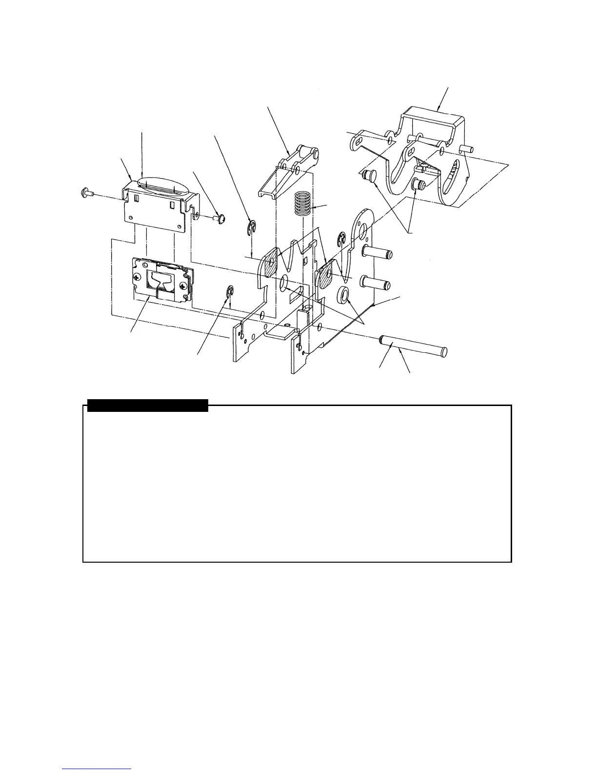
3. FRAME ASSY.
1. Slide the Clincher Assy. into the vertical groove of the front part of the Frame Unit (70F) in the
direction shown in the diagram, then place the Table (70F) over the top and fix it to the Frame Unit
(70F) using the Screws 3x6 (CF) at the left and right.
2. Mount the Spring 3585 in the position shown in the diagram in the center of the Frame Unit (70F).
Place the Clincher Link Assy. on top, and insert the Clincher Link Shaft through it to set the Clincher
Link Assy. in the Frame Unit (70F). Fix the other end of the Clincher Link Shaft with the E-ring 4 CF.
(Apply silicone grease MOLYCOTE EM-30L to the two holes in the Frame Unit and the two holes in
the Clincher Link Assy.)
3. Set the Link Assy. into the Frame Unit (70F) in the direction shown in the diagram. Then insert the
two Link Center Shafts-CF from inside the Link Assy. out through the Frame Unit (70F) at the left
and right, and fix them on the outside of the Frame Unit (70F) using the two E-rings 5 CF. (Apply
silicone grease MOLYCOTE EM-30L to the Link Center Shafts-CF.)
4. Apply silicone grease MOLYCOTE EM-30L to the two Drive Shaft holes in the central part of the
Frame Unit. (Two holes at the left and right.)
ASSEMBLY PROCEDURE
LINK CENTER SHAFT-CF
(EH16440)
FRAME UNIT (70F)
(EH70469)
SPRING 3585
(KK23585)
SCREW 3x6 (CF)
(AA04502)
E-RING 5 CF
(JJ10512)
Confirm that there is a
cutout here.
CLINCHER LINK ASSY.
E-RING 4 CF
(JJ10509)
CLINCHER ASSY.
TABLE (70F)
(EH17388)
CLINCHER LINK SHAFT-CF
(EH16441)
 Loading...