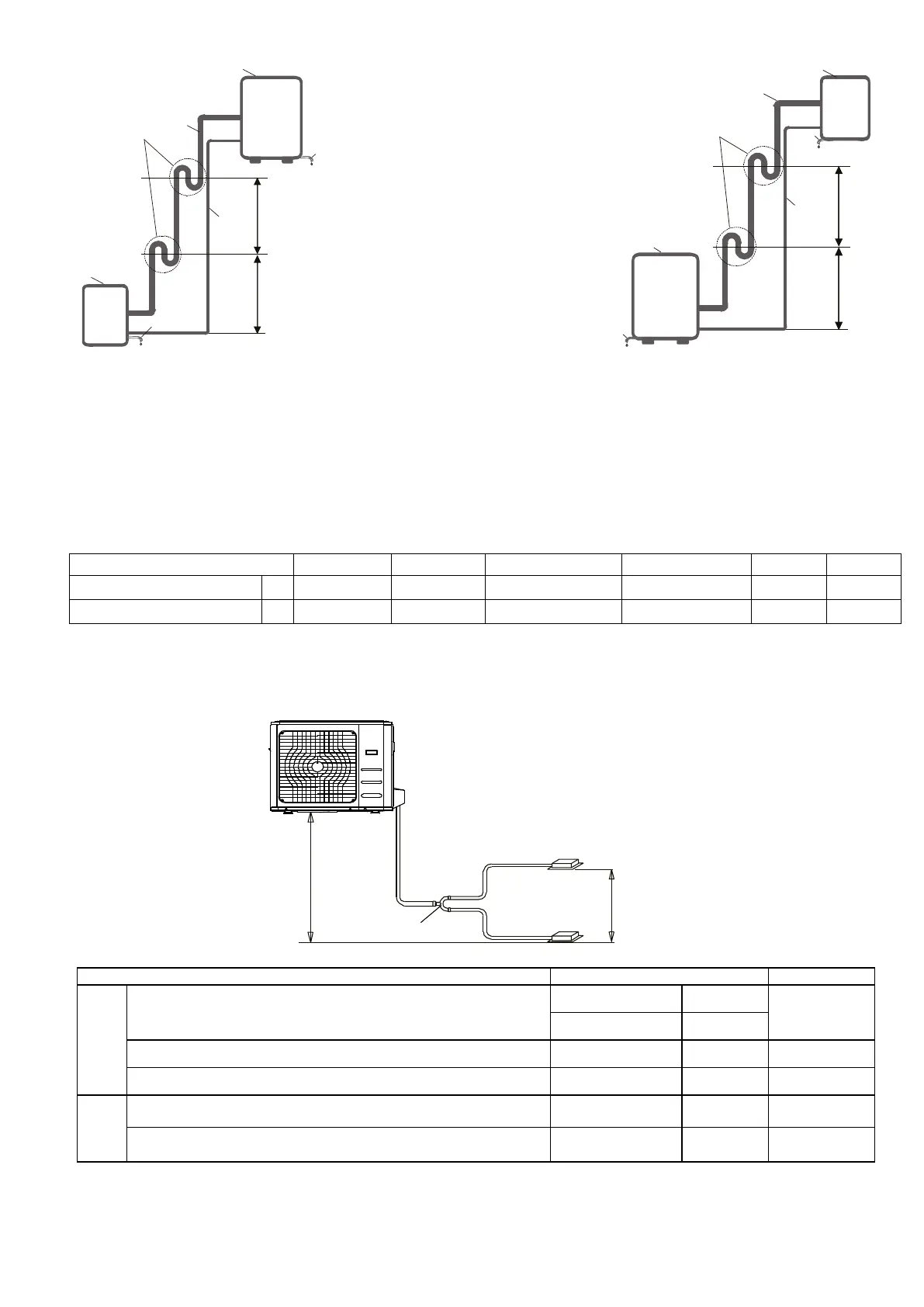
10.4 Connection diagram of the system
1. Outdoor unit
2. Indoor unit
3. Gas pipe side (higher diameter)
4. Liquide pipe side
5. Draining pipe
6. Siphon
■ Outdoor unit above and indoor unit below
In this case, the inlet pipe (3) must be provided with
siphons (6) every 6 meters of level difference. These
siphons are to enable the return of the oil to the
compressor. The connection pipes must be insulated.
■ Outdoor unit below and indoor unit above
In this case, a siphon (3) must be crea
intake pipe (6) every 10 meters to block the flow of
refrigerant and thus to avoid return of liquid to the
compressor.
The connection pipes must be insulated.
N.B.: The maximum height difference between the indoor and the outdoor units must not exceed the values indicated
in the below table.
Max. refrigerant pipe length m 30 50 65 65 65 65
Max. difference in level m 20 25 30 30 30 30
Attention: Wrappipe insulating material around the joint and secure it with plastic straps to avoid condensation
forming at the joints.
■ Outdoor units with TWIN function (on some models)
L
L1
L2
H2 ≤20m
The line branch pipe
Indoor unit
Outdoor unit
H1≤0.5m
Indoor unit
Pipe Length
Total pipe length (Actual)
5300 W + 5300 W 30m
L+Max(L1,L2)
7100 W + 7100 W 50m
Max. branch pipe length 15m L1, L2
Max. branch pipe length difference 10m L1-L2
Drop
Height
Max. height difference between indoor unit and outdoor unit 20m H1
Max. height difference between indoor units 0.5m H2
The branching pipe must be installed horizontally, error angle of it should not large than 10°. Otherwise, malfunction
will be caused.
25