• Select copper pipes for gas and liquid, as indicated in the relative table (see the specifications of the refrigerant
pipes table).
• Before assembling the pipe and its insulation, cover both ends of the pipe to protect it from dust and moisture.
• Try to avoid bending the pipes. If necessary, the radius of curvature can be over 100mm.
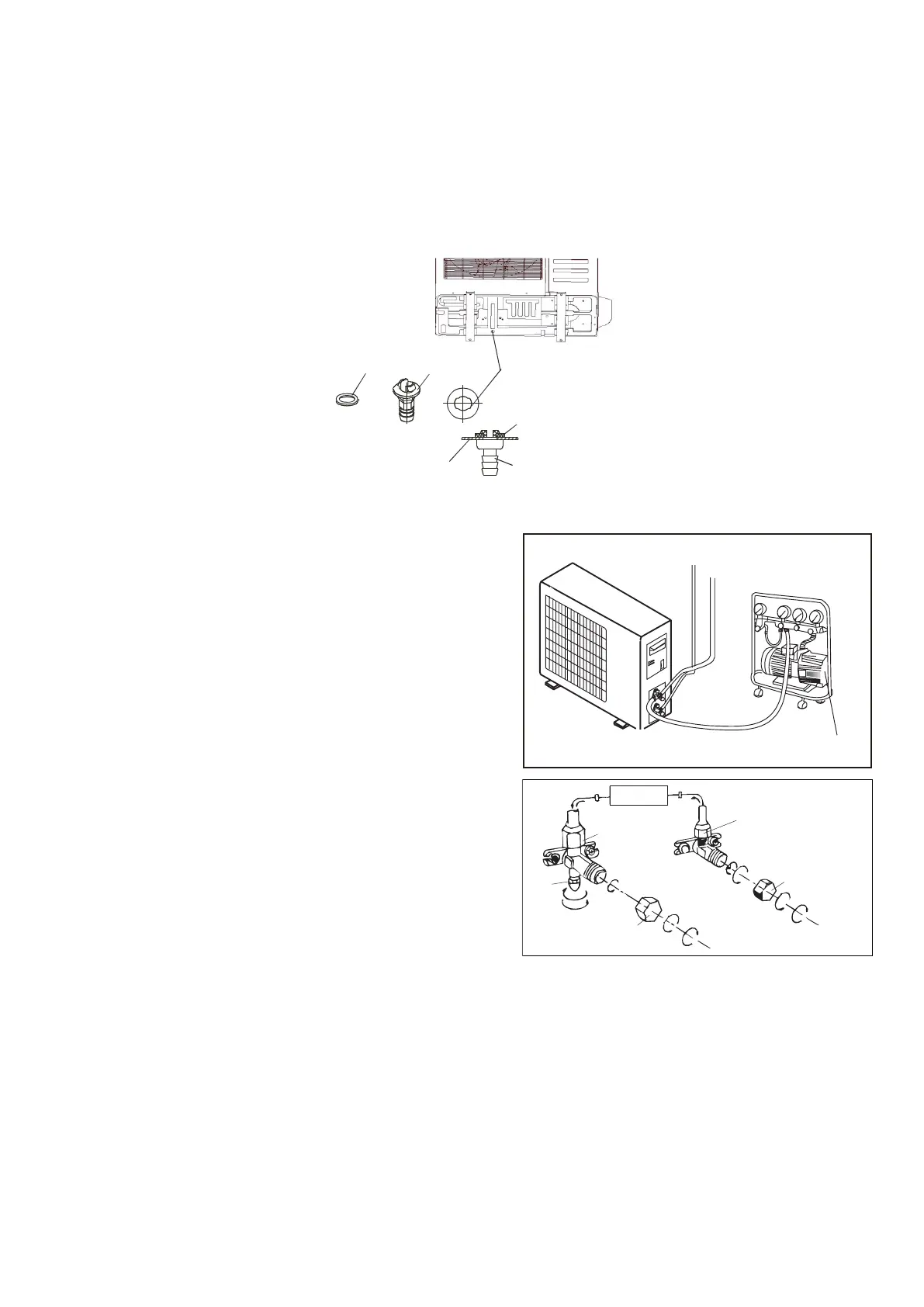
10.9 Installation of the drain joint and the condensate drain hose
Fit the seal into the drain joint, then insert the drain joint into the base pan hole of outdoor, rotate 90 to securely
assemble them. Connect the drain joint with an extension drain hose (Locally purchased), in case of the condensate
draining off the outdoor unit during the heating mode.
Seal
The base pan hole
of outdoor unit
Drain joint
Seal
The base pan
of outdoor unit
Drain
joint
10.10 Vacuum pump
Humid air left inside the refrigerant circuit can cause
compressor malfunction. After having connected the indoor
and outdoor units, bleed the air and humidity from the
refrigerant circuit using a vacuum pump.
1)
Unscrew and remove the caps from the 2-way and 3-way
valves.
2)
Unscrew and remove the cap from the service valve.
3)
Connect the vacuum pump hose to the service valve.
4)
Operate the vacuum pump for 10-
absolute vacuum of 10 mm Hg has been reached.
5)
With the vacuum pump still in operation, close the low-
pressure knob on the vacuum pump coupling.
vacuum pump.
6)
Open the 2-way valve by 1/4 turn and then close it after 10
seconds. Check all the joints for leaks using liquid soap or an
electronic leak device.
7)
Turn the body of the 2-way and 3-way valves. Disconnect
the vacuum pump hose.
8)
Replace and tighten all the caps on the valves (see
paragraph 10.7 for tightening torque).
INDOOR
UNIT
Connect to the
indoor unit
Refrigerant fluid di
rection of fiow
3-way valve
2-way valve
inlet
(2)T
urn
(8) Secure
(7)Turn to open fully
(2)
Turn
(8) Secure
(6) Openby 1/4 turn
(7)
Turn to open fully
(2)Turn
(8) Secure
V
alve cap
Valve cap
Service
27