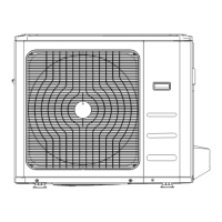
10.11 ELECTRICAL CONNECTIONS
Dissemble the bolts from the cover. (If there isn't a cover on the outdoor unit,
disassemble the bolts from the maintenance board, and pull it in the direction
of the arrow to remove the protection board.) (Refer to figure in the right)
■ Connect the connective cables to the terminals as identified with their
respective mached numbers on the terminal block.
■ Re-install the cover of the electric box.
10.11.1 Specifications of the power supply and cables
MODELS (W) 3500 5300 7100 10500 10500 14000 17600
INDOOR UNIT POWER
OUTDOOR UNIT POWER
INDOOR/OUTDOOR CONNECTING WIRING (mm²)
2-core shielded wire 2x0.2
The power cord type designation is H07RN-F
10.11.2 Electrical Wiring diagrams
CAUTION
The wiring diagram of the air-conditioner are shown as follows. When wiring, please choose the
corresponding figure, or it may cause damage.
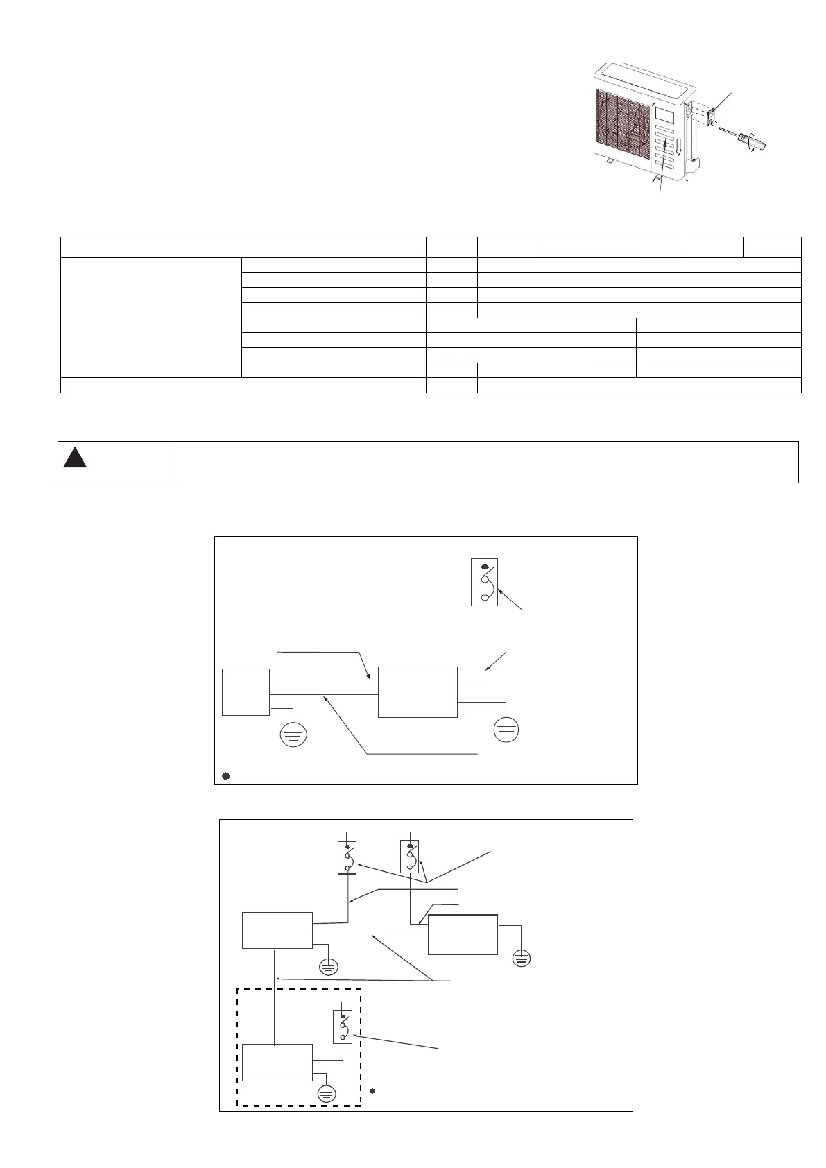
■ Single-line diagram
Mod. 3500 W
Switch/Fuse
(Available locally)
Power linking wiring (Outdoor)
Power supply
Ground the airconditioner properly in case to affect its anti-interference function
Ground wiring
Ground wiring
Elec
-si
gnal link wiring
P
owe
r link
ing
wi
r
ing
(
i
ndoor
un
i
t
)
Outdoor unitIndoor
unit
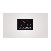
Mod. 5300 W – 17600 W
Ground wiring
Ground wiring
Ground wiring
Switch
/ Fuse
(Available loc
ally)
Switch / Fuse
(Available locally)
Power wiring
(indoor)
Power linking wiri
ng (Outdoor)
Weak elec-signal link wiring
Indoor
Unit
Indoor
Unit
Outdoor
Unit
Po
wer supplyPower supply
Power supply
Ground the airconditioner properly in case
to affect its anti-interference function
28