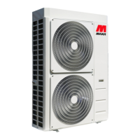
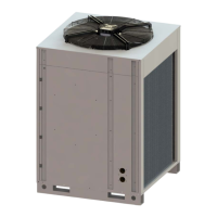
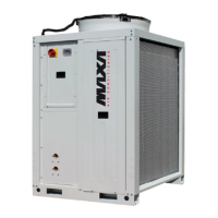
i-32V5 Air/water inverter heat pumps with axial fansi
35
Measure Completed Notes
11
• On no account use possible sources of ignion for refrigerant detecon or
leak detecon.
• Flame leak detectors or other detectors with open ames must not be used.
12
The following leak detecon processes are suitable for systems with ammable
refrigerants:
Leak detecon with electronic refrigerant detectors:
• Electronic refrigerant detectors may not have the required sensi- vity or
may need to be calibrated to the relevant range. Carry out the calibraon in
refrigerant-free surroundings.
• The refrigerant detector must be suitable for the R32 refriger- ant to be de-
tected.
• The refrigerant detector must not contain any potenal sources of ignion.
• Calibrate the refrigerant detector to the refrigerant used. Set the response
threshold to < 3 g/a, suitable for propane.
Leak detecon with liquid leak detectors:
• Liquid leak detectors are suitable for use with most refrigerants.
! Please note
Liquid leak detectors containing chlorine may react with
the refrigerant. This could result in corrosion.
Do not use liquid leak detectors that contain chlorine.
Measures to take if a leak in the refrigerant circuit occurs:
• Immediately exnguish all open ames in the vicinity of the heat pump.
• If brazing/soldering work needs to be undertaken to remedy the leak, al-
ways extract all the refrigerant from the refrigerant circuit. Purge the site
to be brazed/soldered before and during the braz- ing/soldering work with
oxygen-free nitrogen.
13
When breaking into the refrigerant circuit to make repairs – or for any other
purpose – convenonal procedures shall be used. However, it is important that
best pracce is followed since ammability is a consideraon. The following pro-
cedure shall be adhered to:
- remove refrigerant;
- purge the circuit with inert gas;
- evacuate;
- purge again with inert gas;
- open the circuit by cung or brazing.
The refrigerant charge shall be recovered into the correct recovery cylinders. The
system shall be “ushed” with OFN to render the unit safe. This process may
need to be repeated several mes. Compressed air or oxygen shall not be used
for this task.
Flushing shall be achieved by breaking the vacuum in the system with OFN and
connuing to ll unl the working pressure is achieved, then venng to atmo-
sphere, and nally pulling down to a vacuum. This process shall be repeated unl
no refrigerant is within the system. When the nal OFN charge is used, the sys-
tem shall be vented down to atmospheric pressure to enable work to take place.
This operaon is absolutely vital if brazing operaons on the pipe-work are to
take place.
Ensure that the outlet for the vacuum pump is not close to any ignion sources
and there is venlaon available.
14
In addion to convenonal charging procedures, the following requirements
shall be followed.
• Ensure that contaminaon of dierent refrigerants does not occur when
using charging equipment. Hoses or lines shall be as short as possible to
minimise the amount of refrigerant contained in them.
• Cylinders shall be kept upright.
• Ensure that the refrigeraon system is earthed prior to charging the system
with refrigerant.
• Label the system when charging is complete (if not already).
• Extreme care shall be taken not to overll the refrigeraon system.
Before recharging, the system shall be pressure tested with OFN. The system
should be leak tested aer recharging but before commissioning. An addional
leak test must be performed before leaving the site.



 To Next Page