Do you have a question about the MAXA i-HP Series and is the answer not in the manual?
Confirms unit compliance with EU Directive 2006/42/CE and other harmonized standards.
Guidelines for manual upkeep, access, and interpretation of graphic symbols.
Procedures and recommendations for ensuring worker safety during operation and maintenance.
Mandatory personal protective equipment for operating and maintaining the unit.
Explanation and identification of safety signs and symbols present on the unit.
Detailed safety information regarding the R410A refrigerant used in the unit.
Description of the unit's frame materials, construction, and protective treatments.
Details on the refrigerant circuit, including valves, filters, and safety devices.
Information on the type, design, and operation of the DC inverter compressors.
Description of the air-side and user-side heat exchangers and the fan motor.
Details on the electrical control panel, its components, and the unit's control system.
Overview of sensors and devices for monitoring unit operation and safety.
Description of the integrated hydronic kit, including its components and function.
Explanation of fan speed control and the Enhanced Vapour Injection (EVI) technology.
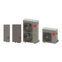
Information on different unit models, capacities, and their configuration codes.
List and description of optional accessories that can be added to the unit.
Essential instructions and warnings for the safe and correct installation of the unit.
Procedures for safely lifting and handling the unit, complying with accident prevention regulations.
Recommendations for unit placement and required minimum clearances for operation and maintenance.
Overview of hydraulic connection requirements and components.
Detailed description and diagrams of the hydraulic circuit, including connections and loading.
Information on drainage connections for condensate and defrost water.
Steps and warnings for charging and topping up the plant hydraulic circuit.
Schematic diagram of the refrigerant circuit for i-HP 0125 and i-HP 0135 models.
Schematic diagram of the refrigerant circuit for the i-HP 0250F model.
Schematic diagram of the refrigerant circuit for i-HP 0250, 0260, and 0270 models.
Schematic diagram of the refrigerant circuit for the i-HP-LT 0125 model.
Schematic diagram of the refrigerant circuit for the i-HP-LT 0235 model.
Schematic diagram of the refrigerant circuit for the i-HP-LT -0250 model.
Connection details for the unit's main power supply.
Description of terminals for user inputs, remote controls, and sensors.
Explanation of the PM module's function for phase sequence detection and protection.
Details on the terminal block for the optional plant management module.
Step-by-step guide for powering on the unit and initial checks.
Information for users regarding unit identification and contacting technical assistance.
Instructions for properly shutting down the unit for extended periods to prevent damage.
Schedule and procedures for routine checks and maintenance of the unit.
Guidelines for handling refrigerants and protecting the environment during operation.
Recommendations for the proper dismantling and disposal of the unit at the end of its life cycle.