49
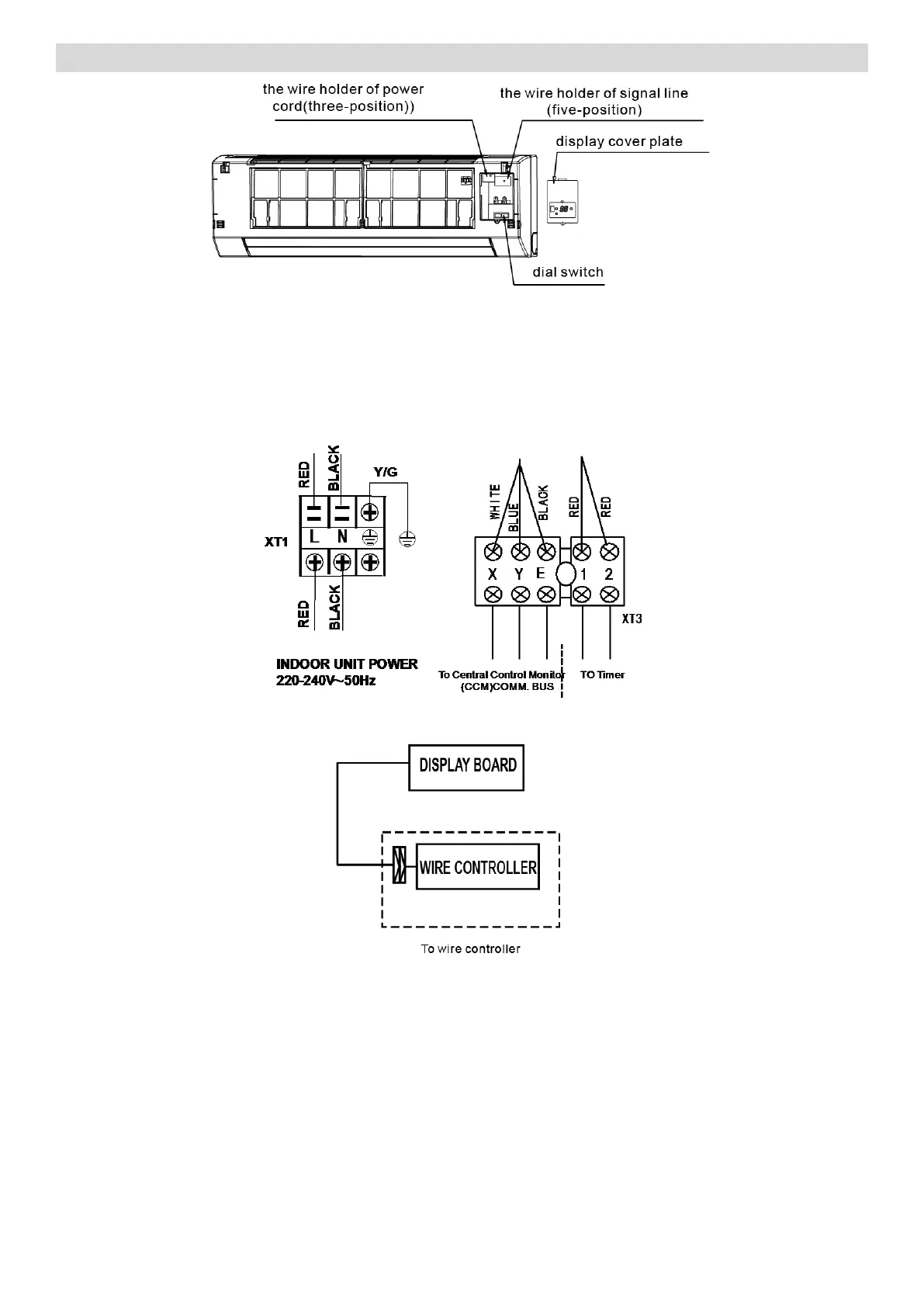
12.5.1 Terminal Board Diagram
Please refer to the indoor unit wiring diagram for the wiring.
Note:
The air-conditioners can connect with Central Control Monitor (CCM). Before operation, please wiring
correctly and set system address and network address of indoor units.
Single phase indoor unit:
Please adopt the shielded twisted-pair wire, and connect the shielded layer to E.
MAXA DC Fan Coil Unit