MAXEONSOLARTECHNOLOGIES,LTD.
SafetyandInstallationInstructions‐Document544753Rev.A
©2022MaxeonSolarTechnologies,Ltd.Allrightsreserved.Specificationsincludedintheseinstructionsaresubjecttochangewithoutnotice.Page|6
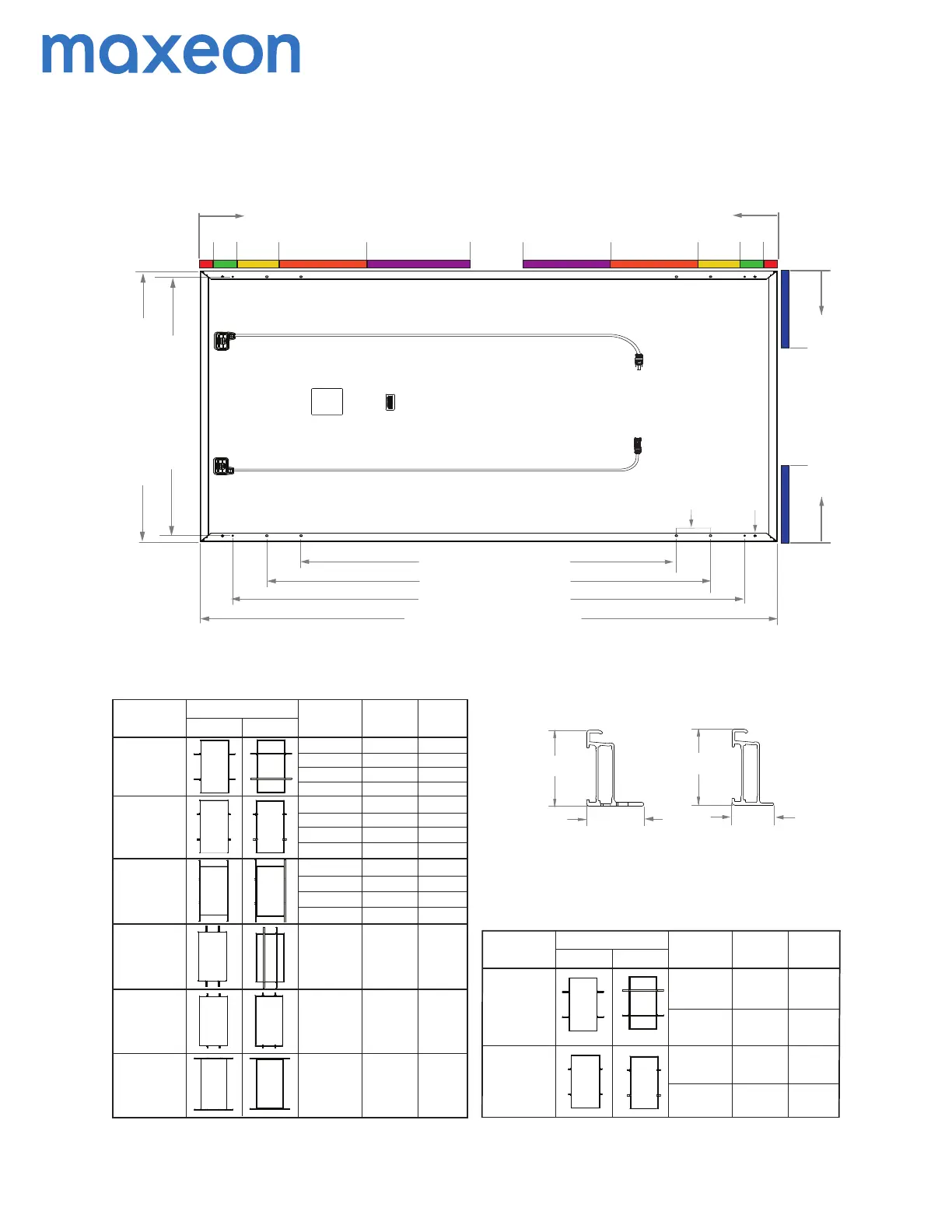
Appendix: Mounting Configurations and Load Ratings
Mounng
Configuraon
Descripon
Mounng Configuraon Diagram
Front View
Back View
Mounng Zone
Locaons
(distance from corner
in mm)
50 - 150
Long Side Mounng,
Point Supported
Long Side Mounng,
Rails Parallel to
Mounng Frame
Short Side Mounng,
Point Supported
(End Mount)
Short Side Mounng,
Rails Parallel to
Mounng Frame
(End Mount)
150 - 272
50 - 150
150 - 272
272 - 453
453 - 710
50 - 150
150 - 272
272 - 453
453 - 710
0 - 350
0 - 350
+2700/-2700
+2700/-2700
+2700/-2700
+1800/-1800
+1800/-1800
+1800/-1800
+3600/-3600
+5400/-4200
+3600/-3600
+2700/-2700
+3600/-2400
+5400/-4200
+3600/-3600
+2700/-2700
+3600/-2400
+5400/-4200
+3600/-3600
+2700/-2700
+2400/-2400
+3600/-2800
+2400/-2400
+1800/-1800
+2400/-1600
+3600/-2800
+2400/-2400
+1800/-1800
+2400/-1600
+3600/-2800
+2400/-2400
+1800/-1800
TOP CLAMPS
Maxeon 3 112 cells AC Ready Solar Panel
(SPR-MAX3-XXX-R, SPR-MAX3-XXX-BLK-R, SPR-MAX3-XXX-COM-R)
GEN 5.2 FRAME PROFILE
SIDE FRAME PROFILE
END FRAME PROFILE
A - Ground Holes (4X Ø4.2mm)
B - Mounng Holes (8X Ø6.8mm)
1046 mm [41.8in]
1002 mm [39.43in]
1100 mm [43.31in]
1300 mm [51.18in]
1656 mm [65.17in]
1812 mm [71.34in]
0
B
272
[10.71]
453
[17.83]
150
[5.91]
710
[27.95]
0
272
[10.71]
453
[17.83]
150
[5.91]
710
[27.96]
0
350
[13.78]
0
A
50
[1.97]
50
[1.97]
350
[13.78]
Mounng
Configuraon
Descripon
Mounng Configuraon Diagram
Front View
Back View
Mounng Zone
Locaons
(distance from corner
in mm)
1300mm Holes
Long Side Mounng,
Rails Perpendincular
to Mounng Frame
Long Side Mounng,
Point Supported
+5400/-5400
+5400/-5400
+5400/-5400
+3600/-3600
+3600/-3600
+3600/-3600
1100mm Holes
BOLTS
1300mm Holes
1100mm Holes
+5400/-5400
+3600/-3600
Measurement Tolerances are +/-3 mm for the Length and Width of the Module.
4 Rails must not be under the juncon box.
2 Test loads are for informaon purposes only, design loads should be considered for the project design.
C
overe
d
und
e
r
IE
C 61
730
Cert T
es
t
f
o
r
104
cel
l
5 In the cases where hybrid mounng is necessary (combinaon of long and short side mounng), the lowest
design load values should be considered as allowable design load.
Design Load considers 1.5 Factor of Safety, Test load = Design load x 1.5. Product Warranty covers only design
load values. The design loads listed in this table supersede all other loads that may be defined by other
pares, unless there is a formal authorizaon by Maxeon.
Short Side Mounng,
Rails Perpendicular to
Mounng Frame
(End Mount)
0 - 350
272 - 453
453 - 710
Long Side Mounng,
Rails Perpendincular
to Mounng Frame
Tes t Lo ad
Downward/Upward
(Pa)
Tes t Lo ad
Downward/Upward
(Pa)
Design Load
Downward/Upward
(Pa)
Design Load
Downward/Upward
(Pa)
32 mm
[1.26in]
40 mm
[1.57in]
40 mm
[1.57in]
24 mm
[0.94in]
6 Boom flange mounng.
 Loading...