MAXEONSOLARTECHNOLOGIES,LTD.
SafetyandInstallationInstructions‐Document544753Rev.A
©2022MaxeonSolarTechnologies,Ltd.Allrightsreserved.Specificationsincludedintheseinstructionsaresubjecttochangewithoutnotice.Page|7
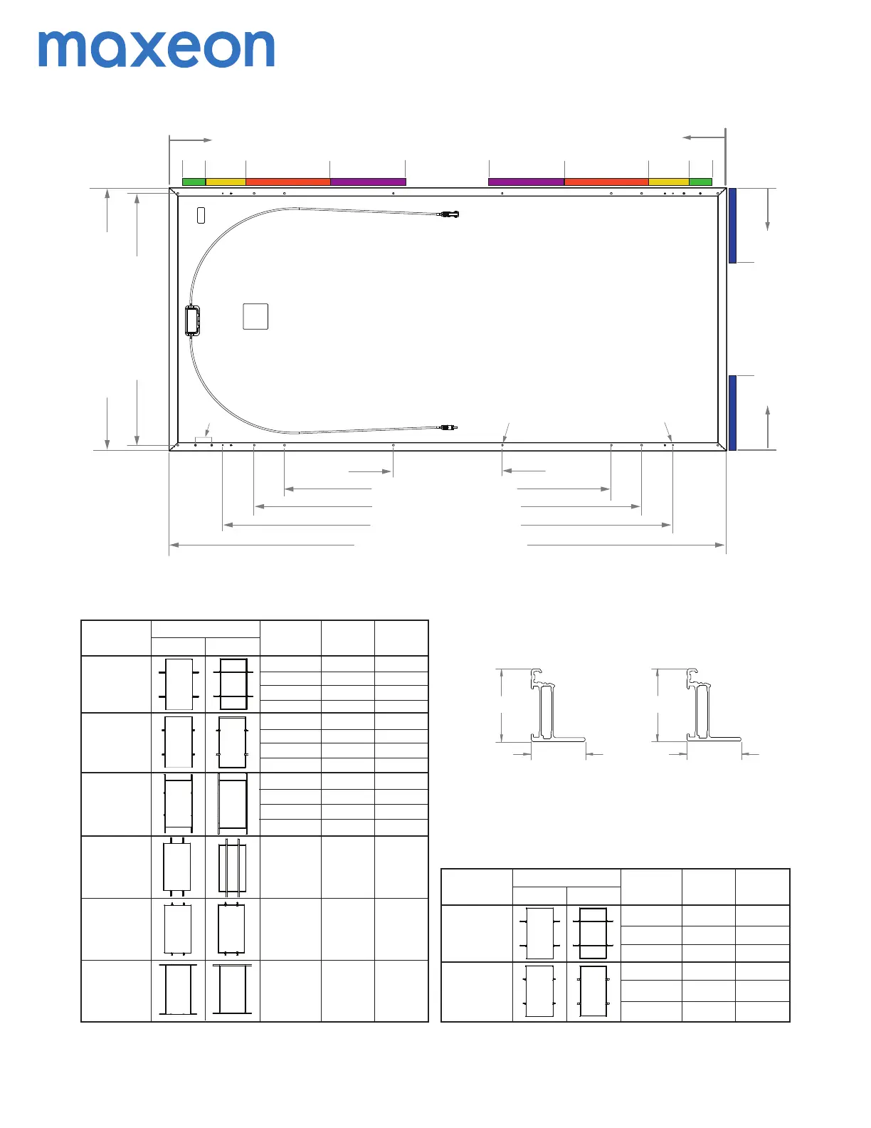
GEN 5.6 FRAME PROFILE
A - MLSD Holes
B - Mounng Holes (16X Ø6.8mm)
C - Ground Holes (4X Ø4.2mm)
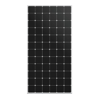
Maxeon 6 72 cells Commercial Solar Panel
(SPR-MAX6-XXX-COM)
1039 mm [40.91in]
995 mm [39.17in]
400 mm
[15.74in]
1200 mm [47.24in]
1423 mm [56.02in]
1653 mm [65.08in]
2047 mm [80.59in]
0
A
B
C
SIDE FRAME PROFILE
END FRAME PROFILE
50
[1.97]
0
50
[1.97]
296
[11.65]
536
[21.10]
150
[5.91]
825
[32.48]
0
0
350
[13.78]
32 mm
[1.26in]
35 mm
[1.38in]
32 mm
[1.26in]
35 mm
[1.38in]
350
[13.78]
825
[32.48]
536
[21.10]
296
[11.65]
150
[5.91]
Mounng Configuraon Diagram
Front View
Back View
Mounng Zone
Locaons
(distance from corner
in mm)
50 - 150
Long Side Mounng,
Point Supported
Long Side Mounng,
Rails Parallel to
Mounng Frame
Short Side Mounng,
Point Supported
(End Mount)
Short Side Mounng,
Rails Parallel to
Mounng Frame
(End Mount)
150 - 296
296 - 536
536 - 825
50 - 150
150 - 296
296 - 536
536 - 825
50 - 150
150 - 296
296 - 536
536 - 825
0 - 350
0 - 350
0 - 350
+2400/-1600
+1800/-1600
+1800/-1600
+1200/-1067
+1200/-1067
+1600/-1067
+2400/-2400
+5400/-2400
+2400/-2400
+1800/-1800
+2400/-2400
+5400/-2400
+2400/-2400
+1800/-1800
+2400/-2400
+5400/-2400
+2400/-2400
+1800/-1800
+1600/-1600
+3600/-1600
+1600/-1600
+1200/-1200
+1600/-1600
+3600/-1600
+1600/-1600
+1200/-1200
+2600/-1600
+3600/-1600
+1600/-1600
+1200/-1200
TOP CLAMPS/INVISIMOUNT
Tes t Loa d
Downward/Upward
(Pa)
Design Load
Downward/Upward
(Pa)
Mounng
Configuraon
Descripon
Short Side Mounng,
Rails Perpendicular to
Mounng Frame
(End Mount)
Long Side Mounng,
Rails Perpendincular
to Mounng Frame
Mounng Configuraon Diagram
Front View
Back View
Mounng Zone
Locaons
(distance from corner
in mm)
1423mm Holes
Long Side Mounng,
Rails Perpendincular
to Mounng Frame
Long Side Mounng,
Point Supported
1200mm Holes
400mm Holes
+2500/-2400
+5400/-5400
+5400/-5400
+2400/-2400
+5400/-6000
+5400/-6000
+1600/-1600
+3600/-3600
+3600/-3600
+1600/-1600
+3600/-4000
+3600/-4000
1423mm Holes
1200mm Holes
400mm Holes
BOLTS
Tes t Loa d
Downward/Upward
(Pa)
Design Load
Downward/Upward
(Pa)
Mounng
Configuraon
Descripon
2 Test loads are for informaon purposes only, design loads should be considered for the project design.
3 This configuration was cert tested to +9000/-4500 Pa
Design Load considers 1.5 Factor of Safety, Test load = Design load x 1.5. Product Warranty covers only design
load values. The design loads listed in this table supersede all other loads that may be defined by other
pares, unless there is a formal authorizaon by Maxeon.
4 Rails must not be under the juncon box.
5 In the cases where hybrid mounng is necessary (combinaon of long and short side mounng), the lowest
design load values should be considered as allowable design load.
Measurement Tolerances are +/-3 mm for the Length and Width of the Module.
6 Boom flange mounng
 Loading...