CAUTION!
To prevent personal injury:
• Always disconnect the plug from the power source when
making any adjustments.
• The adjustment must be correct. If it is not, kickback could
result in a serious injury and inability to make accurate cuts.
3332
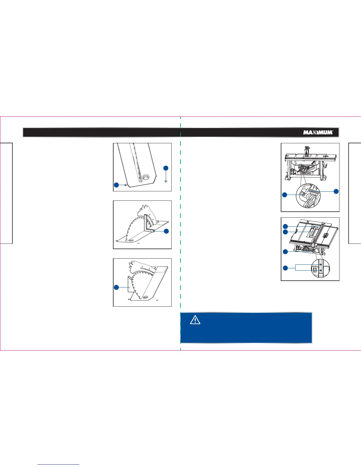
ADJUSTING THE BEVEL STOPS (Fig. 25-27)
This saw has positive stops that will quickly position
the saw blade at 90° or 45° to the table.
The angle settings of the saw have been set at the
factory and, unless damaged in shipping, should not
require setting during assembly. After extensive use,
it may need to be checked. Make adjustments only if
necessary.
• Unplug the saw.
• Remove the anti-kickback pawls assembly and
blade guard assembly.
• Raise the blade to the maximum height by turning
the height-adjusting knob clockwise.
• Using a framing square (1), set the blade to exactly
90°.
• If the blade stops bevelling before it gets to 90°,
loosen the 90°-stop set screw (2) (located at the
left of the table insert), and then adjust it to 90°.
• With the blade set at 90°, slowly turn the 90°-stop
set screw (2) until you feel resistance. Bevel the
blade away from 90° a little, and then back to the
stop.
• Re-measure the angle and repeat the stop
adjustment as necessary until the blade stops at
90°.
• Set the 45° stop in the same way. The 45°-stop set
screw (3) is located at the right of table insert. Use
the triangle square (4).
• Replace the anti-kickback pawls assembly and
blade guard assembly.
• Make a test cut.
ADJUSTING THE BEVEL INDICATOR (Fig. 28)
If the bevel indicator (1) is not at 0° when the saw
blade is at 90°, adjust the indicator (1) by loosening
the cross screw (2) with a star-head screwdriver and
setting it to 0° on the bevel scale.
Retighten the cross screw (2).
Make sure that you make a trial cut on a scrap
piece of wood before making critical cuts. Measure
for exactness.
CHECKING THE ALIGNMENT OF THE RIP
FENCE TO THE BLADE (Fig. 29)
• Unplug the saw.
• Remove the blade guard assembly and anti-kickback
pawls assembly.
• Raise the locking handle (1) to allow the rip
fence (2) to be moved.
• Place the framing square (3) beside the blade, and
move the rip fence up to the square. Note the
measurement on the rip scale.
• Move the fence back and rotate the framing square
(3) 180° to check the other side.
• If the two measurements are not the same, loosen
the two socket head bolts (4) on the rip fence and
then align it.
• Retighten the two socket head bolts (4).
• Replace the blade guard assembly and anti-kickback
pawls assembly.
• Make two or three test cuts using scrap wood. If the
cuts are not true, repeat the process.
model no. 055-6766-2 | contact us 1-888-670-6682
ASSEMBLY
model no. 055-6766-2 | contact us 1-888-670-6682
ASSEMBLY
Fig. 28
Fig. 29
Fig. 25
Fig. 26
Fig. 27
2
3
1
4
1
4
2
1
2
3
 Loading...