NOTE: A 90° cut has a 0° bevel and a 45° cut has a 45° bevel.
WARNING!
Be extremely careful when loosening arbour nut.
Keep firm grasp on both wrenches. Do not allow hands to
slip and contact blade.
3130
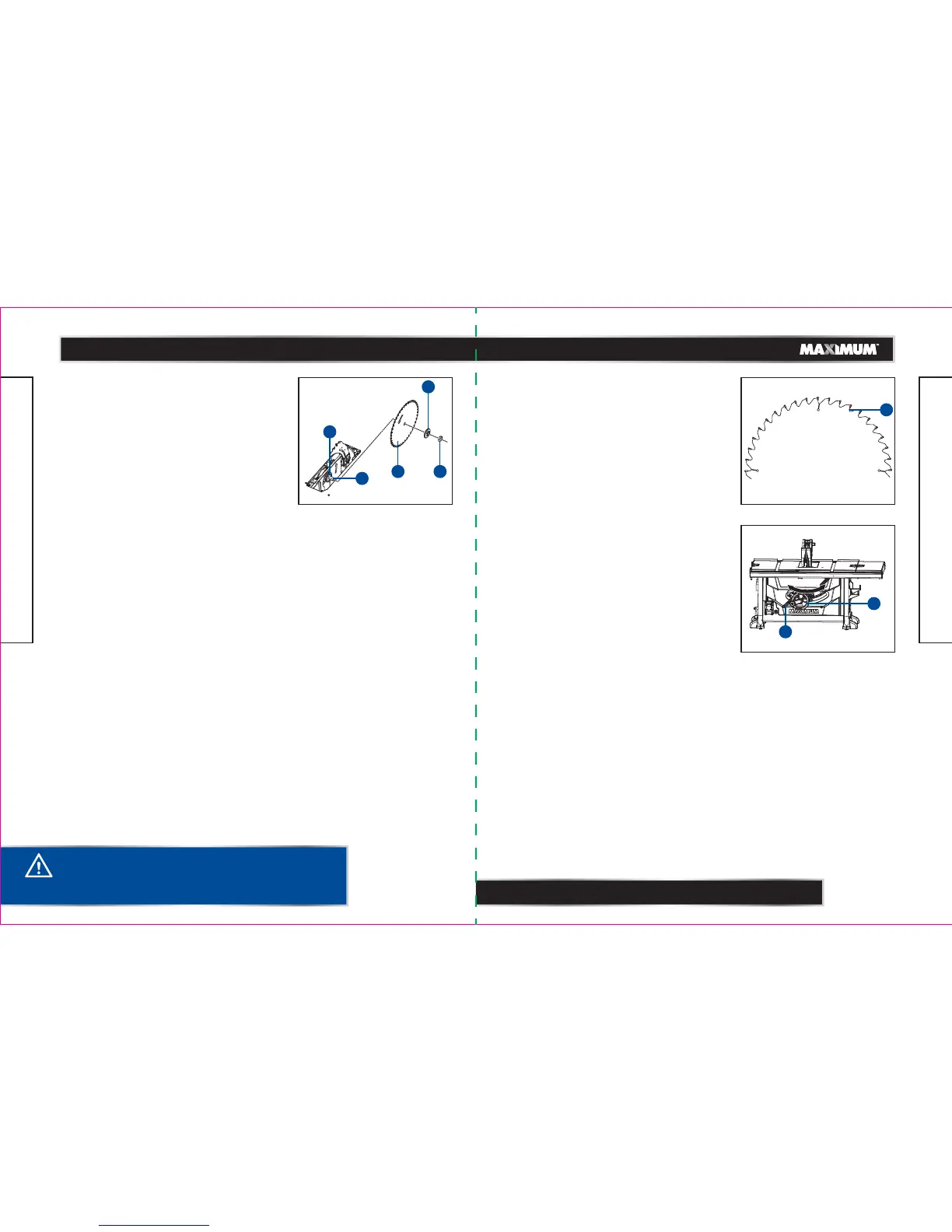
TO REPLACE THE SAW BLADE (Fig. 22)
When you need to replace the saw blade, please
follow the procedure below:
• Unplug the saw.
• Turn height-adjustment knob clockwise to raise
blade to maximum height.
• Remove the blade guard and anti-kickback pawls.
• Remove the table insert.
• Using one opened-ended blade wrench, place the
flat open end on the flats on the outer blade
flange (1).
• Using the other opened-ended blade wrench, place
the flat open end on the flats on the arbour nut (2).
Holding both wrenches firmly, pull the opened-
ended blade wrench on the arbour nut forward to
the front of the machine.
• Remove arbour nut (2), outer blade flange (1) and
saw blade (3).
• Place one new blade on arbour (4). Make sure saw
blade teeth point down at the front side of saw
table. Place outer flange (1) and nut (2) on arbour
and use blade wrenches to tighten nut securely.
Verify that large, flat surface of the outer flange
faces the the saw blade and the saw blade (3) is
firmly seated aganist the inner flange (5).
• Lower the saw blade to lowest position and replace
table insert.
• Replace blade guard assembly and pawl assembly.
CHANGING THE BLADE DEPTH (Fig. 23)
The saw blade depth should be set so that the outer
points of the saw blade are higher than the workpiece
by approximately 1/8 to 1/4" (3.2 to 6.4 mm), but the
lowest points (gullets) (1) are below the top surface.
• Unplug the saw.
• Turn the bevel-locking lever clockwise to tighten it
securely.
• Raise the blade by turning the height-adjusting
knob clockwise, or lower it by turning the knob
counter-clockwise.
CHANGING THE BLADE ANGLE (Fig. 24)
This table saw has a rack-and-pinion bevel control
that allows you make angled cuts from 90° to 45°.
• Unplug the saw.
• Loosen the bevel-locking lever (1) by turning it
counter-clockwise.
• To adjust the bevel angle, turn the height/bevel
adjusting handwheel (2) counter-clockwise
increasing the angle of the blade and bringing it
closer to 45°. Turning it clockwise decreases the
angle, bringing the blade closer to 90°.
• Lock by turning the bevel-locking lever (1)
clockwise.
model no. 055-6766-2 | contact us 1-888-670-6682
ASSEMBLY
model no. 055-6766-2 | contact us 1-888-670-6682
ASSEMBLY
Fig. 23
Fig. 24
1
Fig. 22
1
23
4
5
2
1
 Loading...