Fig. 41
Fig. 42
Fig. 43
Fig. 44
Fig. 45
4544
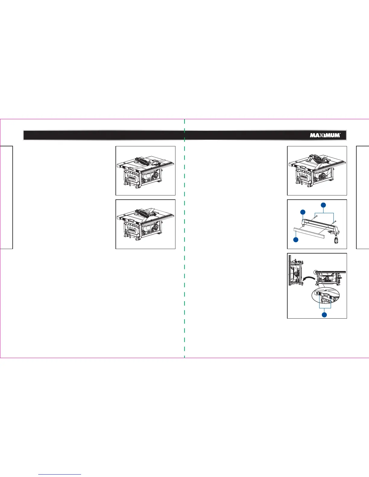
BEVEL CROSSCUTTING 0-45° BLADE BEVEL
AND 90° MITRE ANGLE (Fig. 41)
This cutting operation is the same as crosscutting,
except that the blade is at a bevel angle other than
0°.
This operation must be performed with mitre gauge
in the right side groove.
• Adjust the blade to the desired angle, and then
tighten the blade bevel-locking lever.
• Tighten the mitre lock handle at 90°.
• Hold the workpiece firmly against the face of the
mitre gauge throughout the cutting operation.
Make sure that you always work to the right side
of the blade during this type of cut. The mitre gauge
must be in the right side groove, because the bevel
angle may cause the blade guard to interfere with
the cut if it is used in the left side groove.
0-45° BLADE BEVEL AND 0-45° MITRE ANGLE
(Fig. 42)
This sawing operation combines a mitre angle with
a bevel angle. This operation must be performed
with the mitre gauge in the right side groove.
• Set the mitre gauge to the desired angle.
• Place the mitre gauge in the right side groove of
the table.
• Set the blade bevel to the desired bevel angle, and
tighten the blade bevel-locking lever.
• Hold the workpiece firmly against the face of the
mitre gauge throughout the cutting operation.
Make sure that you always work to the right side of
the blade during this type of cut. The mitre gauge
must be in the right side groove, because the bevel
angle may cause the blade guard to interfere with
the cut if it is used in the left side groove.
MITRING 0-45° MITRE ANGLE (Fig. 43)
This sawing operation is the same as crosscutting,
except that the mitre gauge is locked at an angle
other than 90°.
• Set the blade to the 0° bevel angle, and then
tighten the blade bevel locking lever.
• Set the mitre gauge to the desired mitre angle, and
lock it in position by tightening the mitre gauge
locking handle.
• Hold the workpiece firmly against the face of the
mitre gauge throughout the cutting operation.
USING WOOD FACING ON THE RIP FENCE
(Fig. 44)
When performing certain special cutting operations,
add a wood facing to either side of the rip fence.
• Use a smooth, straight, 3/4" (1.9 cm) thick wooden
facing (1) that is as long as the rip fence.
• Attach the wood facing (1) to the rip fence (2) using
wood screws (3) (not included) through the drilled
hole previously in the fence. A wood facing should
be used when ripping material such as thin paneling,
in order to prevent the material from catching
between the bottom of the fence and the table.
TO STORE THE TABLE SAW VERTICALLY
(Fig. 45)
The table saw can be stored vertically with the left
side of saw on the level surface to occupy a narrower
space when not in use. The rubber mat (1) can better
protect the left side of the work table with its rubber
feet.
Make sure that
you store all the accessories (such as
rip fence, anti-kickback pawls, mitre gauge, etc.)
securely before storing the table saw.
model no. 055-6766-2 | contact us 1-888-670-6682
OPERATION
model no. 055-6766-2 | contact us 1-888-670-6682
OPERATION
1
3
2
1
 Loading...