WARNING!
Do not at any time let brake fluids, gasoline, petroleum-
based products, penetrating oils, etc., come in contact
with plastic parts. Chemicals can damage, weaken or
destory plastic, which may result in serious personal injury.
WARNING!
• When servicing, use only identical replacement parts. Use
of any other parts may create a hazard or cause product
damage.
• For your own safety, turn the switch Off and remove the
key. Remove the plug from the power source before
performing maintenance on or lubricating your saw.
• Before performing any maintenance, make sure the tool
is unplugged from the power supply and the switch is in
the Off (O) position. Failure to heed this warning could
result in serious personal injury.
Fig. 46
4746
GENERAL MAINTENANCE
Avoid using slovents when cleaning plastic parts. Most plastics are susceptible to damage
from various types of commercial solvents and may be damaged by their use. Use clean
cloths to remove dirt, dust, oil, grease, etc.
• Periodically check all clamps, nuts, bolts and screws for tightness and condition. Make
sure the table insert is in good condition and in position.
• Check the blade guard assembly.
• To maintain the table surfaces, fence and rails, periodically apply paste wax to them and
buff them to provide smooth functioning.
• Protect the blade by cleaning out sawdust from underneath the table and in the blade
teeth. Use a resin solvent on the blade teeth.
• Clean plastic parts only with a soft, damp cloth. DO NOT use any aerosol or petroleum
solvents.
LUBRICATION
All of the bearings in this tool are lubricated with a sufficient amout of high-grade
lubricant for the life of the unit under normal operating conditions. Therefore, no further
lubrication is required.
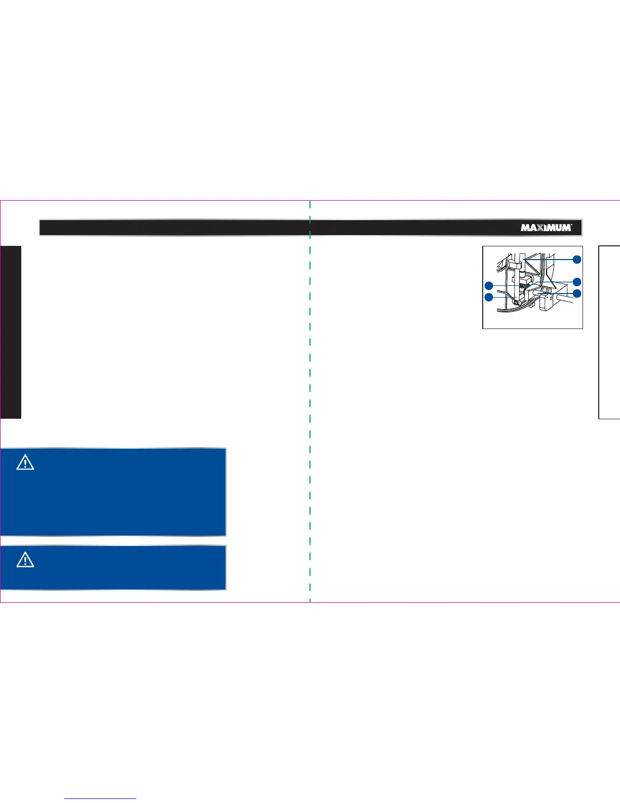
BLADE RAISING AND TILTING MECHANISM
(Fig. 46)
Check the blade raising and tilting mechanism for
looseness, binding, or other abnormalities after
every five hours of operation.
• Unplug the table saw from the power supply outlet
and turn it upside down.
• Turn the screw shaft (1), which connects with the
bevel gear (2), in clockwise or counter-clockwise
direction.
• This turning movement will be transferred to the
vertical guiding rod (3) through the taper gear (4)
and transverse shaft (5), thereby causing the
vertical guiding rod to move up and down.
model no. 055-6766-2 | contact us 1-888-670-6682
MAINTENANCE
model no. 055-6766-2 | contact us 1-888-670-6682
MAINTENANCE
4
4
1
2
3
 Loading...