37
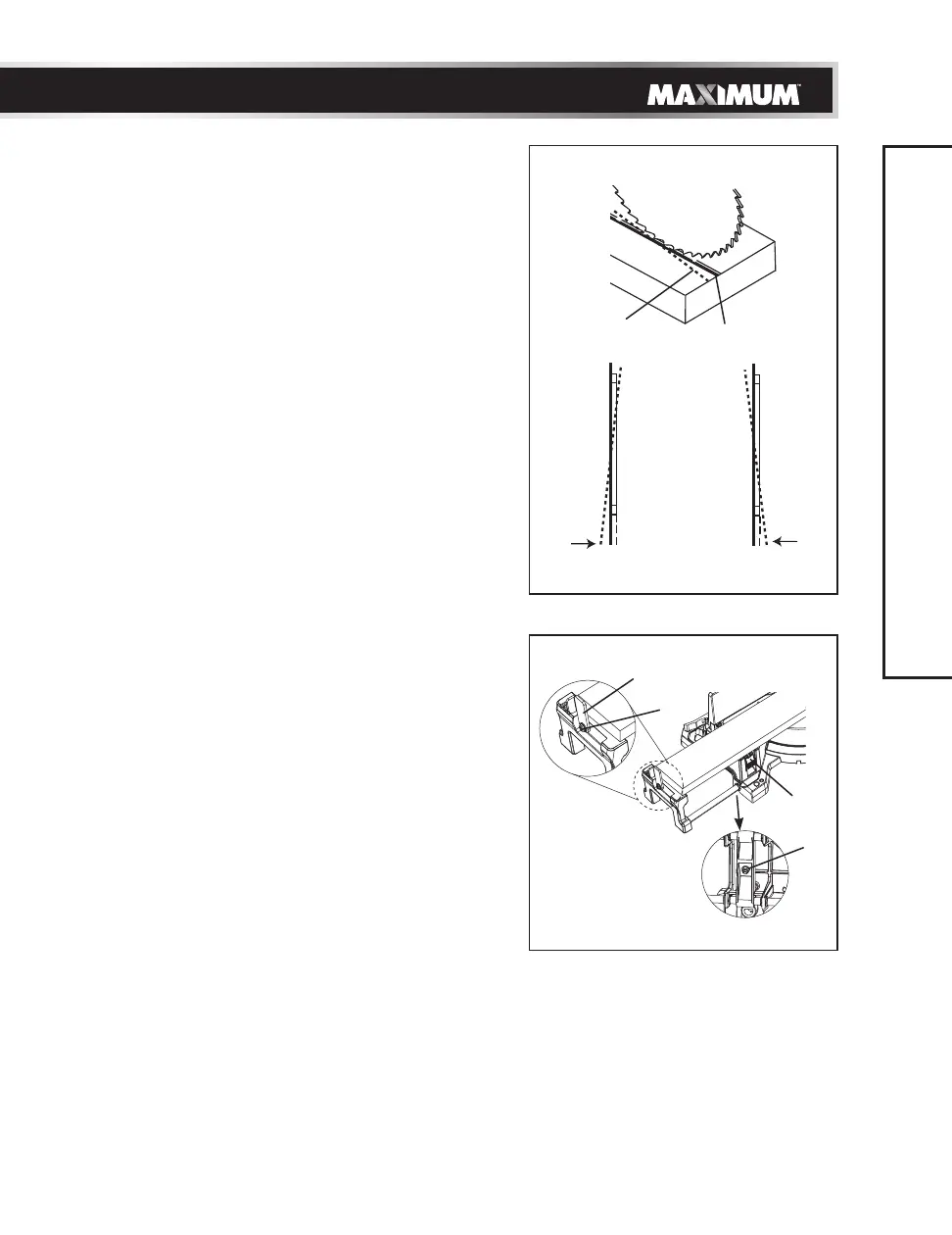
Procedure B (Fig. 29, 31)
• Slightly turn the laser horizontal
adjustment knob (2) to adjust the
horizontal angle of the laser beam on the
top of the board. If the laser beam is out
of parallel from left to right, turn the laser
horizontal adjustment knob (2) clockwise;
If the laser beam is out of parallel from
right to left, turn the laser horizontal
adjustment knob (2) counter-clockwise
until the laser beam is parallel with the
horizontal “pattern line.”
• Recheck the laser beam alignment.
EXTENSION WING USE AND
ADJUSTMENT (Fig. 32)
The left and right side extension wings can
offer extra support for long workpieces.
• Lift the locking lever (1) and pull out the
left extension wing to the desired support
length. Push down on the locking lever (1)
to tighten the extension wing. Repeat for
the right side extension wing if needed.
• If the locking lever (1) will not tighten,
adjust the nut (2), located under the base,
1/4 turn clockwise using a 3/8" (10 mm)
wrench until tight.
REPETITIVE CUTTING USING THE STOP
PLATE (Fig. 32)
The stop plate is designed for making
repetitive cuts of the same length.
NOTE: Use only one stop plate at a time,
NEVER use both stop plates.
• Rotate the stop plate (3) to vertical
position.
• If stop plate will not rotate, loosen
the locking screw (4) 1/4 turn using a
screwdriver and 8 mm wrench.
Fig. 31
Laser beam Pattern line
Counter-clockwise Clockwise
Fig. 32
1
4
3
2
ADJUSTMENTS