11921 Slauson Ave. Santa Fe Springs, CA. 90670 (800) 227-4116 FAX (888) 771-7713
23
TORSION
SPRING
PIN
CORRECTLY POSITIONED
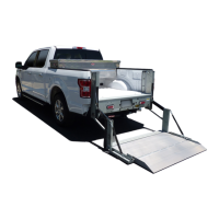
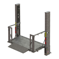
PLATFORM & FLIPOVER
FIG. 23-1A
“H”
SUPPORT
BLOCK
PIN LOCATION
FIG. 23-1
FREE
LEG
3. Position platform and fl ipover to 90 degrees,
+2 / -0 degrees (FIG. 23-1). Get a second
person to hold the platform in place while
you take measurements.
4. On RH side of platform, position the torsion
spring so it rests on pin (FIGS. 23-1 and
23-1A). Make sure free leg of torsion spring
is parallel to chamfered surface on support
block (FIG. 23-1A). Measure gap “H” be-
tween leg of the torsion spring and support
block (FIG. 23-1A). Get enough 1/16” shim
washers (Kit items), to equal measured gap.
To prevent possible injury and damage to Liftgate, have another qualifi ed
person hold platform in position to keep it from falling open.
WARNING
!
 Loading...