EasyManua.ls Logo

Maxon BMR Series User Manual

Maxon BMR Series
106 pages
To Next Page IconTo Next Page
Page #1 background imageLoading...
Page #1 background image
M-16-10
REV. D
MARCH 2020
• Warnings & Safety Instructions
• Requirements - Body Strength & Installed Liftgate
• Liftgate Installation Components
• Liftgate Component Installation Instructions
• Hydraulic Fluid Filling Instructions
• Decals
• Hydraulic & Electrical System Diagrams
• Pre-delivery Inspection Form
Installation Manual Contains:
© MAXON Lift Corp. 2020
To nd maintenance & parts information for your BMR Liftgate, go
to www.maxonlift.com. Click the PRODUCTS, COLUMNLIFT &
BMR buttons. Open the Maintenance Manual in the PRODUCT
DOCUMENTATION window. For parts, click on the PARTS PORTAL,
COLUMNLIFT & BMR buttons.

Table of Contents

Question and Answer IconNeed help?

Do you have a question about the Maxon BMR Series and is the answer not in the manual?

Maxon BMR Series Specifications

General IconGeneral
BrandMaxon
ModelBMR Series
CategoryLifting Systems
LanguageEnglish

Summary

Summary of Changes

Warnings and Safety

General Warnings

Crucial safety warnings for liftgate installation and operation, including PPE and environmental hazards.

Safety Instructions

Essential safety guidelines for liftgate installation and operation, emphasizing understanding manuals and safe practices.

Vehicle Requirements

Body Strength

Details the forces exerted on vehicle body by liftgate and strength requirements.

Clearance Dimensions

Illustrates critical clearance dimensions for liftgate installation on different vehicle types.

Installed Liftgate Orientation

Specifies correct liftgate column orientation relative to level ground for proper operation.

Liftgate Installation Components

Components List

Step 1: Prepare Vehicle If Required

Step 2: Choose Method of Installation

Method 1: Pre-Install Mounting Plates

Weld mounting plates and extension plate to vehicle body before bolting liftgate.

Method 2: Weld Bolt-On Liftgate to Body

Assemble mounting plates to liftgate at factory, then weld liftgate to vehicle body.

Method 3: Weld Liftgate to Body

Weld liftgate with extension plate directly to vehicle body.

Step 3: Position Liftgate

Method 1: Pre-Install Plates

Position and weld mounting plates and extension plate onto the vehicle body.

Method 2: Weld Bolt-On Liftgate

Position and weld the bolt-on liftgate to the vehicle body using angle stock.

Method 3: Weld Liftgate

Position and weld liftgate to vehicle body using angle stock.

Step 4: Bolt Liftgate to Vehicle

Method 1: Pre-Installed Plates

Bolt liftgate to vehicle using pre-installed mounting plates and extension plate.

Step 5: Remove Lower Support Fixtures

Step 6: Position Pump Box Frame

Step 7: Attach Pump & Battery Box Frame to Vehicle

Step 8: Run Hydraulic Lines & Electric Cables

Run Gravity Down Hydraulic Lines

Route hydraulic hoses for gravity down operation, connecting columns to the pump box.

Torque Values for Hydraulic Connectors

Specifies correct torque values for various hydraulic hose connectors.

Run Power Down Hydraulic Lines

Route hydraulic hoses for power down operation, connecting columns to the pump box.

Run Electric Cables

Connect electrical cables, including control switches, harnesses, and taillight connectors.

Step 9: Ground Pump to Vehicle Frame

Step 10: Run Charge Lines

Recommended Power Configurations

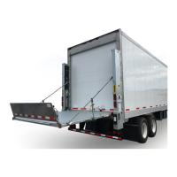
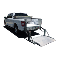
Illustrates typical installation of liftgate, pump, and battery boxes on trailers and trucks.

Running Cable from Vehicle Battery

Procedure for installing charge lines from vehicle battery to pump box or battery box.

Step 11: Connect Charge Lines & Batteries

Step 12: Pressurize Hydraulic System

Step 13: Optimize Hydraulic Fluid Level

Step 14: Remove Upper Support Fixtures

Step 15: Securing Columns

Method 1 & Method 2

Secure columns using lock plates and nuts for bolt-on installation methods.

Method 1 Only

Tighten cap screws and bolt extension plate if needed for Method 1 installation.

Step 16: Finish Welding Liftgate to Vehicle

Method 2 & 3: Weld Liftgate to Body

Complete welding operations for liftgate installation using Methods 2 and 3.

Step 17: Check Clearance of Connector Bar Side Brackets & Stop Blocks

Step 18: Check Clearance of Runner Pads

Step 19: Platform Chain Adjustment

Step 20: Adjust Platform Assembly

Step 21: Place “Align Arrows” Decal

Step 22: Activate Platform Lights

Decals & Plates

Decal Sheet

Provides part numbers and descriptions for various decals used on the liftgate.

Touch Up Galvanized Finish

Hydraulic System Diagrams

Pump & Motor Solenoid Operation - Power Down

Details solenoid operation for power down mode, including valve energization.

Pump & Motor Solenoid Operation - Gravity Down

Details solenoid operation for gravity down mode, including valve energization.

Gravity Down Hydraulic Schematic

Schematic illustrating the hydraulic system for gravity down liftgate operation.

Power Down Hydraulic Schematic

Schematic illustrating the hydraulic system for power down liftgate operation.

Electrical System Diagrams

Interconnecting Electrical Schematic - Gravity Down

Wiring diagram for interconnecting components in gravity down systems.

Gravity Down Single & Dual Pump Electrical Schematic

Electrical schematic for gravity down systems with single or dual pumps.

Interconnecting Electrical Schematic - Power Down

Wiring diagram for interconnecting components in power down systems.

Power Down Single & Dual Pump Electrical Schematic

Electrical schematic for power down systems with single or dual pumps.

BMR Electrical Values

Pre-Delivery Inspection Form

Related product manuals