13
11921 Slauson Ave. Santa Fe Springs, CA. 90670 (800) 227-4116 FAX (888) 771-7713
FIG. 13-1
DESCRIPTION
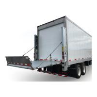
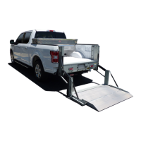
1 BMR Liftgate
2
Hardware parts bag, mounting bracket parts bag, hydraulic lines & fi ttings, wiring
harness, power cable, molded switch control box
3A Mounting plates (bolt-on installation kit)
3B Extension plate (bolt-on installation kit)
4 Pump box assembly
5A Pump installation kit (3’, 10’, 15’, 20’, or 28’)
5B Channel guard (for 10’, 15’, 20’ or 28’ installation kits only)
6
Frame for pump box with optional battery box is shown. A shorter frame is also
available for mounting single pump box or an optional battery box.
7 Battery box (optional)
8
Optional equipment
9
Installation and operation manuals.
TABLE 13-1
2
3B
5A
6
7
4
3A
3A
5B
1
8
9
LIFTGATE INSTALLATION COMPONENTS
Each BMR Liftgate includes items
shown in FIG. 13-1.

 Loading...