47
11921 Slauson Ave. Santa Fe Springs, CA. 90670 (800) 227-4116 FAX (888) 771-7713
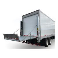
STEP 8 - RUN HYDRAULIC LINES & ELECTRIC CABLES
NOTE: The hydraulic cylinders in the Liftgate are fi lled with hydraulic fl uid and bled
at the factory. To keep air out of the hydraulic system, follow instructions
carefully for installing hydraulic system components.
NOTE: The fold and unfold hydraulic hoses are identical hoses. To avoid confu-
sion when running hoses through the channel, MAXON recommends tap-
ing both ends of one of the hoses for easy identifi cation.
Always route hydraulic hoses and electrical wiring clear of moving parts,
brake lines, sharp edges and exhaust systems. Avoid making sharp bends in
hoses and wiring. Make sure that bends in the electrical wiring are 1” or more
away from electrical connector. Attach securely. If drilling is necessary, fi rst
check behind the drilling surface so you do not damage any fuel lines, vent
lines, brake lines or wires.
CAUTION
!
1. Get hydraulic hoses, hydraulic tee, channel guard (if required) and plastic ties from
parts box and pump box installation kit. Run hydraulic hoses from LH and RH columns
to pump box. Connect hydraulic hoses as shown in FIG. 48-1 and TABLES 49-1 and
49-2 for Gravity Down Liftgate or FIG. 51-1 and TABLES 52-1 and 52-2 for Power
Down Liftgate.
2. Get interconnect harness from pump box installation kit. Run the interconnect harness
from pump box to RH and LH columns as shown in FIG. 53-1.
3. If channel guard is required, bolt up one side of the channel (FIGS. 48-1, 51-1 and
53-1) to vehicle body. Leave bolts loose until all hydraulic hoses (FIGS. 48-1 and 51-1)
and wiring harness (FIG. 53-1) are run through channel. After hoses and wiring har-
ness are run, bolt up second side of channel and tighten all bolts and nuts. Use plastic
ties to secure runs of hydraulic hoses and wiring harness that are outside of channel
guard.

 Loading...