Page 10 of 10 M-KIT100/101/102 Assembly Instrucons 181-03001
These instrucons must be followed exactly. Failure to follow these instrucons could damage the product or result in injury to persons using or
assembling the product. Maxon Furniture Inc. shall not be liable for any costs, loss, damage, expenses or injuries resulng from failure to properly
assemble the product in accordance with these instrucons.
Maxon Furniture Inc. Customer Service: 1-800-876-4274
Unpack the Worksurface UWR2472TM and 1.
hardware kit.
TIP! Be sure to lay the Worksurface on a
so surface unl you are ready to install
it.
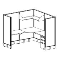
Unscrew the Canlever Brackets from the 2.
Worksurface.
Install two RH Canlever Brackets in the right 3.
hand slots of Panels A & B at about 28” from
the oor (Figure 14).
With the Canlever lted up at about 45°, 4.
slide the top tooth into the panel slot, then
rotate the Canlever down to engage the
other teeth (Figure 15).
Install the LH Canlever Bracket in the le 5.
side of panel A as instructed in Steps 3 - 4
(Figure 14).
Aach the Worksurface to the LH and RH 6.
Canlever Brackets using three #10 x 3/4”
Pan Head Screws in each Canlever Bracket
(Figure 16).
TIP! A total of nine #10 x 3/4” Pan Head
Screws will be used.
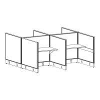
Adding the Worksurface
Figure 16
28"
RH Cantilever
Bracket
LH Cantilever
Bracket
(hidden)
Panel A
Panel B
#10 x 3/4" Pan Head screw
(3 per Bracket, 9 total)
LH Cantilever Bracket
Figure 14
Figure 15