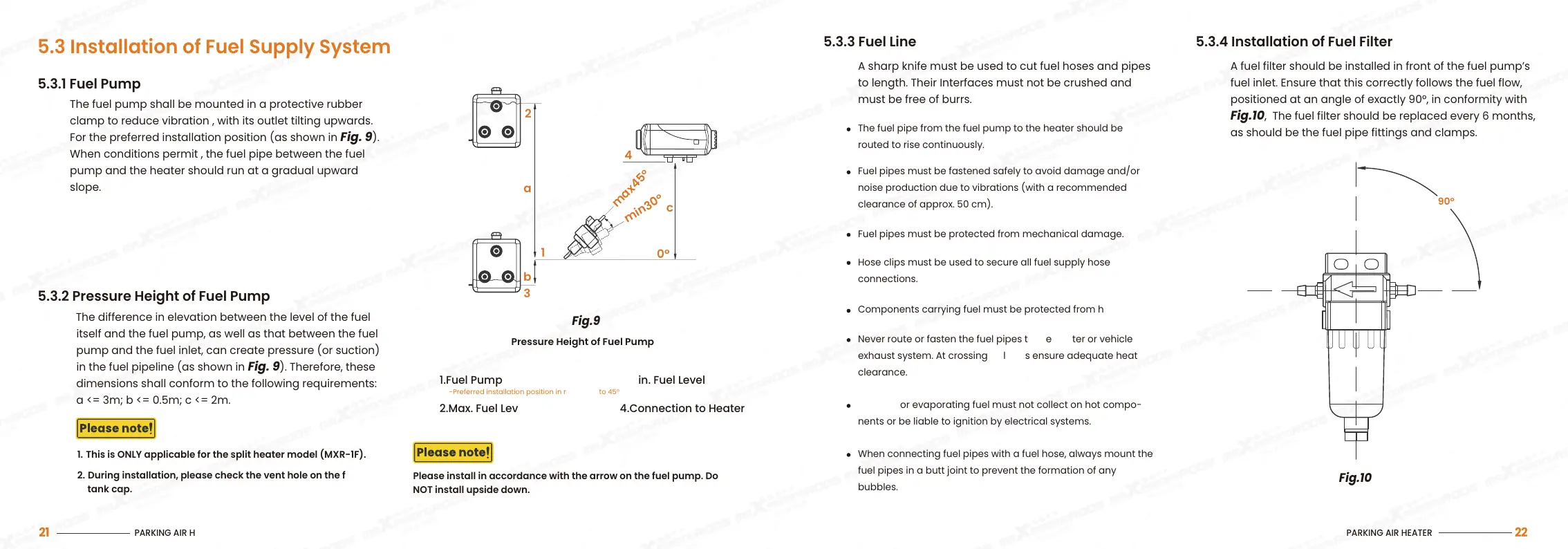
Fig.10
5.3.3 Fuel Line 5.3.4 Installation of Fuel Filter
A fuel filter should be installed in front of the fuel pump’s
fuel inlet. Ensure that this correctly follows the fuel flow,
positioned at an angle of exactly 90°, in conformity with
Fig.10, The fuel filter should be replaced every 6 months,
as should be the fuel pipe fittings and clamps.
A sharp knife must be used to cut fuel hoses and pipes
to length. Their Interfaces must not be crushed and
must be free of burrs.
The fuel pipe from the fuel pump to the heater should be
routed to rise continuously.
Fuel pipes must be fastened safely to avoid damage and/or
noise production due to vibrations (with a recommended
clearance of approx. 50 cm).
Never route or fasten the fuel pipes to the heater or vehicle
exhaust system. At crossings, always ensure adequate heat
clearance.
Dripping or evaporating fuel must not collect on hot compo-
nents or be liable to ignition by electrical systems.
When connecting fuel pipes with a fuel hose, always mount the
fuel pipes in a butt joint to prevent the formation of any
bubbles.
Hose clips must be used to secure all fuel supply hose
connections.
Components carrying fuel must be protected from heat.
Fuel pipes must be protected from mechanical damage.
90°
Pressure Height of Fuel Pump
1.Fuel Pump
2.Max. Fuel Level
3.Min. Fuel Level
4.Connection to Heater
Please install in accordance with the arrow on the fuel pump. Do
NOT install upside down.
-Preferred installation position in range 30° to 45°
Fig.9
5.3 Installation of Fuel Supply System
5.3.1 Fuel Pump
The fuel pump shall be mounted in a protective rubber
clamp to reduce vibration , with its outlet tilting upwards.
For the preferred installation position (as shown in Fig. 9).
When conditions permit , the fuel pipe between the fuel
pump and the heater should run at a gradual upward
slope.
max45°
min30°
2
4
1
3
0°
a
c
b
5.3.2 Pressure Height of Fuel Pump
The difference in elevation between the level of the fuel
itself and the fuel pump, as well as that between the fuel
pump and the fuel inlet, can create pressure (or suction)
in the fuel pipeline (as shown in Fig. 9). Therefore, these
dimensions shall conform to the following requirements:
a <= 3m; b <= 0.5m; c <= 2m.
1. This is ONLY applicable for the split heater model (MXR-1F).
2.
During installation, please check the vent hole on the fuel
tank cap.
PARKING AIR HEATER
22
PARKING AIR HEATER
21